background image

Page 10

For technical questions, please call 1-800-444-3353.

SKU’s 40072, 

40073, & 97521

Note:

  Some parts are listed and shown for illustration purposes only and are not available 

individually as replacement parts.

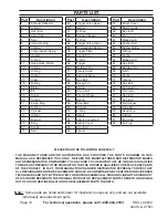
PARTS LIST

PLEASE READ THE FOLLOWING CAREFULLY

 THE MANUFACTURER AND/OR DISTRIBUTOR HAS PROVIDED THE PARTS DIAGRAM IN THIS 

MANUAL AS A REFERENCE TOOL ONLY.  NEITHER THE MANUFACTURER NOR DISTRIBUTOR MAKES 

ANY REPRESENTATION OR WARRANTY OF ANY KIND TO THE BUYER THAT HE OR SHE IS QUALIFIED 

TO MAKE ANY REPAIRS TO THE PRODUCT OR THAT HE OR SHE IS QUALIFIED TO REPLACE ANY PARTS 

OF THE PRODUCT.  IN FACT, THE MANUFACTURER AND/OR DISTRIBUTOR EXPRESSLY STATES THAT 

ALL REPAIRS AND PARTS REPLACEMENTS SHOULD BE UNDERTAKEN BY CERTIFIED AND LICENSED 

TECHNICIANS AND NOT BY THE BUYER. THE BUYER ASSUMES ALL RISK AND LIABILITY ARISING OUT 

OF HIS OR HER REPAIRS TO THE ORIGINAL PRODUCT OR REPLACEMENT PARTS THERETO, OR ARISING 

OUT OF HIS OR HER INSTALLATION OF REPLACEMENT PARTS THERETO.

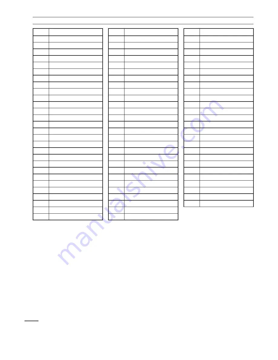
Part

Description

1

Exhaust Deflector

2

O-Ring

3

Hex. Bolt

4

Head Cap

5

Seal

6

Internal Lining

7

O-Ring

8

Compression Spring

9

Gasket

10

O-Ring

11

Head Valve Piston

12

O-Ring

13

O-Ring

14

O-Ring

15

Collar

16

O-Ring

17

Piston

18

Pin

19

Driver

20

O-Ring

21

Lining Ring

22

O-Ring

23

Cylinder

24

O-Ring

25

Bumper

26

Body

27

Nozzle

28

Seal

Part

Description

29

Trigger Valve Upper

30

Spring

31

O-Ring

32

Trigger Plunger

33

O-Ring

34

Trigger Valve Lower

35

Compression Spring

36

Trigger Plate

37

Spring Pin

38

E-Ring

39

Trigger

40

Retainer Pin

41

Safety Guide

42

Spring Washer

43

Hex Bolt

44

Spring Pin

45

Spring

46

Screw Nut

47

Thumb Wheel

48

Spring

49

Steel Ball

50

Stopper

51

E-Ring

52

Safety

53

Safety Cover Bolt

54

Safety Cover

55

Hex. Bolt

56

Spacer

Part

Description

57

Driver Cover

58

Driver Guide

59

Hex. Bolt

60

Pin

61

Magazine B

62

Pusher Unit

63

Spring Holder

64

O-Ring

65

Spring

66

Magazine A

67

Hex. Bolt

68

Retainer Pin

69

Latch

70

Spring

71

O-Ring

72

Hex Bolt

73

Cylinder Pin

74

Tail Cover

75

Hex. Bolt

76

Hex. Bolt

77

Tail Hanger

78

Lock Nut

79

Hand Grip

80

O-Ring

81

End Cap

82

Air Plug

Summary of Contents for AIR STAPLER 1/4" CROWN, 18 GAUGE 97521

Page 1: ...ll rights reserved No portion of this manual or any artwork contained herein may be reproduced in any shape or form without the express written consent of Harbor Freight Tools Diagrams within this man...

Page 2: ...t in death or serious injury CAUTION used with the safety alert symbol indicates a hazardous situation which if not avoided could result in minor or moderate injury NOTICE is used to address practices...

Page 3: ...ses the risk of injury to persons as a result of being caught in moving parts c Avoid unintentional starting Be sure the trigger is released before connecting to the air supply Do not carry the tool w...

Page 4: ...serviced before using Many accidents are caused by poorly maintained tools There is a risk of bursting if the tool is damaged h Use only accessories that are identified by the manufacturer for the sp...

Page 5: ...onnect the tool from the air supply when a Unattended b Performing any maintenance or repair c Clearing a jam d Moving the tool to a new location 13 Do not make any modifications to this tool 14 Refer...

Page 6: ...annot cover all possible conditions and situations that may occur It must be understood by the operator that common sense and caution are factors which cannot be built into this product but must be su...

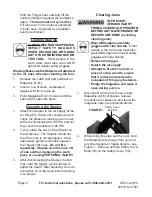
Page 7: ...put 3 5 drops of pneumatic tool oil in the Air Plug 82 before each use Testing the Single Sequential Safety Trip Mechanism Warning Even though the Stapler should be empty during this procedure ALWAYS...

Page 8: ...not fire if the nose is not depressed Once depressed gently and briefly squeeze the Trigger 39 once Do not fire repeatedly Staples could bounce off of one another damaging the work piece or causing P...

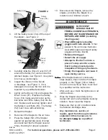
Page 9: ...Disconnect the Stapler remove the staples and store the Stapler in a location out of children s reach MAINTENANCE TO PREVENT SERIOUS INJURY FROM ACCIDENTAL OPERATION BEFORE ANY MAINTENANCE OR REPAIRS...

Page 10: ...INSTALLATION OF REPLACEMENT PARTS THERETO Part Description 1 Exhaust Deflector 2 O Ring 3 Hex Bolt 4 Head Cap 5 Seal 6 Internal Lining 7 O Ring 8 Compression Spring 9 Gasket 10 O Ring 11 Head Valve Pi...

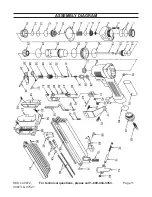
Page 11: ...Page 11 For technical questions please call 1 800 444 3353 SKU s 40072 40073 97521 ASSEMBLY DIAGRAM...

Page 12: ...low the exclusion or limitation of incidental or consequential damages so the above limitation of exclusion may not apply to you THIS WARRANTY IS EXPRESSLY IN LIEU OF ALL OTHER WARRANTIES EXPRESS OR I...

Reviews:

Related manuals for AIR STAPLER 1/4" CROWN, 18 GAUGE 97521