background image

Page 7

For technical questions, please call 1-800-444-3353.
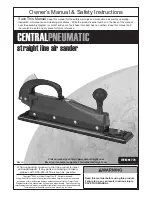
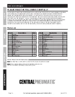
Item 91773 


SAFETY

OPERA

TION

MAINTENANCE

SETUP

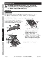
Initial Tool Set Up/Assembly

  Read the ENTIRE IMPORTANT SAFETY INFORMATION section at the beginning of this 

manual including all text under subheadings therein before set up or use of this product.

Note:

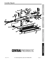
 For additional information regarding the parts listed in the following pages, 

refer to the Assembly Diagram near the end of this manual.

Note:

 This air tool may be shipped with a protective plug covering the air inlet.  Remove this plug before set up.

Air Supply

TO PREVENT SERIOUS INJURY FROM EXPLOSION: 

Use only clean, dry, regulated, compressed air to power this tool.   

Do not use oxygen, carbon dioxide, combustible gases,  

or any other bottled gas as a power source for this tool.

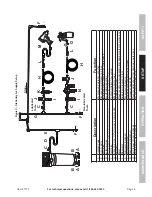
1.  Incorporate a filter, regulator with pressure gauge, 

oiler, in-line shutoff valve, and quick coupler for 

best service, as shown on Figure B on page 8 

and Figure C on page 9. 

 An in-line shutoff 

ball valve is an important safety device because 

it controls the air supply even if the air hose 

is ruptured.  The shutoff valve should be a 

ball valve because it can be closed quickly.

Note: 

If an automatic oiler system is not used, 

add a few drops of Pneumatic Tool Oil to the 

airline connection before operation.  Add a few 

more drops after each hour of continual use.

2.  Attach an air hose to the compressor's air outlet.  

Connect the air hose to the air inlet of the tool.  

Other components, such as a coupler plug 

and quick coupler, will make operation 

more efficient, but are not required.

WARNING!  TO PREVENT SERIOUS INJURY 

FROM ACCIDENTAL OPERATION: 

Do not install a female quick coupler on the tool.


Such a coupler contains an air valve that will 

allow the air tool to retain pressure and operate 

accidentally after the air supply is disconnected.

Note: 

Air flow, and therefore tool performance, can 

be hindered by undersized air supply components.  

The air hose must be long enough to reach 

the work area with enough extra length to 

allow free movement while working.

3.  Release the tool's Trigger.

4.  Close the in-line shutoff valve between 

the compressor and the tool.

5.  Turn on the air compressor according to 

the manufacturer's directions and allow it 

to build up pressure until it cycles off.

6.  Adjust the air compressor's output regulator 

so that the air output is enough to properly 

power the tool, but the output will not exceed 

the tool's maximum air pressure at any time.  

Adjust the pressure gradually, while checking the 

air output gauge to set the right pressure range.

7.  Inspect the air connections for leaks.  

Repair any leaks found.

8.  If the tool will not be used at this time, turn off 

and detach the air supply, safely discharge 

any residual air pressure, and release the 

Trigger to prevent accidental operation.

Note:

 Residual air pressure should not be present 

after the tool is disconnected from the air supply.  

However, it is a good safety measure to attempt to 

discharge the tool in a safe fashion after disconnecting 

to ensure that the tool is disconnected and not powered.

Summary of Contents for CENTRAL PNEUMATIC 91773

Page 1: ...s actual product may differ slightly from the product described herein Tools required for assembly and service may not be included When unpacking make sure that the product is intact and undamaged If any parts are missing or broken please call 1 800 444 3353 as soon as possible Save This Manual Keep this manual for the safety warnings and precautions assembly operating inspection maintenance and c...

Page 2: ...t in minor or moderate injury Addresses practices not related to personal injury IMPORTANT SAFETY INSTRUCTIONS INSTRUCTIONS PERTAINING TO A RISK OF FIRE ELECTRIC SHOCK OR INJURY TO PERSONS WARNING When using tools basic precautions should always be followed including the following General To reduce the risks of electric shock fire and injury to persons read all the instructions before using the to...

Page 3: ...mps or another practical way to secure and support the workpiece to a stable platform Holding the work by hand or against the body is unstable and is able to lead to loss of control 2 Do not force the tool Use the correct tool for the application The correct tool will do the job better and safer at the rate for which the tool is designed 3 Do not use the tool if the switch does not turn the tool o...

Page 4: ...d air pressure or within the rated air pressure range 2 Never use oxygen carbon dioxide combustible gases or any bottled gas as an air source for the tool Such gases are capable of explosion and serious injury to persons SAVE THESE INSTRUCTIONS Symbols and Specific Safety Instructions Symbol Definitions Symbol Property or statement no No load speed min Revolutions or reciprocation per minute PSI P...

Page 5: ... accessory may detach or break during operation 5 Obey the manual for the air compressor used to power this tool 6 Install an in line shutoff valve to allow immediate control over the air supply in an emergency even if a hose is ruptured 7 Use this tool with both hands only Using tools with only one hand can result in loss of control 8 Do not lay the tool down until it has come to a complete stop ...

Page 6: ...I Air Inlet 1 4 18 NPT Maximum Speed 3 000 SPM Air Consumption 6 CFM 90 PSI Recommended Hose Size 3 8 Dia Pad Dimensions 2 3 4 x 15 3 4 Sandpaper size 2 3 4 x 17 1 2 Maximum speed at stated maximum air pressure Excess air pressure is hazardous and may cause the tool to exceed stated maximum speed Figure A Components and Controls Trigger 26 Air Inlet 1 Handle 27 Knob 22 ...

Page 7: ...inlet of the tool Other components such as a coupler plug and quick coupler will make operation more efficient but are not required WARNING TO PREVENT SERIOUS INJURY FROM ACCIDENTAL OPERATION Do not install a female quick coupler on the tool Such a coupler contains an air valve that will allow the air tool to retain pressure and operate accidentally after the air supply is disconnected Note Air fl...

Page 8: ...r Hose Connects air to tool B Filter Prevents dirt and condensation from damaging tool or work piece C Regulator Adjusts air pressure to tool D Lubricator optional For air tool lubrication E Coupler and Plug Provides quick connection and release F Leader Hose optional Increases coupler life G Air Cleaner Dryer optional Prevents water vapor from damaging work piece H Air Adjusting Valve optional Fo...

Page 9: ...bration reduction E Main Air Line 3 4 minimum recommended Distributes air to branch lines F Ball Valve To drain moisture from system G Branch Air Line 1 2 minimum recommended Brings air to point of use H Air Hose Connects air to tool I Filter Prevents dirt and condensation from damaging tool or work piece J Regulator Adjusts air pressure to tool K Lubricator optional For air tool lubrication L Cou...

Page 10: ... serious hazards 2 3 4 x 17 1 2 strips of sandpaper sold separately see Accessory List on page 13 are used with this Inline Sander The sandpaper is held in place at each end of the Sander with toothed clamps and a tension bar Figure D Tension bar Clamp Clamp Tension bar To install the sandpaper 1 Figure E Tension Bar Raise Tension bar Pull up on the tension bar at each end of the Sander 2 Figure F...

Page 11: ...r before use 4 Firmly grip the Handle with one hand and the Knob with the other hand 5 Depress the Trigger before making contact with the work surface to ensure the Inline Sander does not jump from your hands 6 Move the Inline Sander along the work surface in a smooth steady motion Keep the sander moving from side to side to avoid sanding a pattern into the work surface Note Do not put too much pr...

Page 12: ...ate the tool only with specified lubricants Lubricate the air inlet using only pneumatic tool oil Other lubricants may damage the mechanism and may be highly flammable causing an explosion Cleaning Maintenance and Lubrication Note These procedures are in addition to the regular checks and maintenance explained as part of the regular operation of the air operated tool 1 Daily Air Supply Maintenance...

Page 13: ...ing use 1 Incorrect lubrication or not enough lubrication 2 Worn parts 1 Lubricate using air tool oil according to directions 2 Have qualified technician inspect internal mechanism and replace parts as needed Severe air leakage Slight air leakage is normal especially on older tools 1 Cross threaded housing components 2 Loose housing 3 Damaged valve or housing 4 Dirty worn or damaged valve 1 Check ...

Page 14: ...ARISING OUT OF HIS OR HER REPAIRS TO THE ORIGINAL PRODUCT OR REPLACEMENT PARTS THERETO OR ARISING OUT OF HIS OR HER INSTALLATION OF REPLACEMENT PARTS THERETO Parts List Record Product s Serial Number Here Note If product has no serial number record month and year of purchase instead Note Some parts are listed and shown for illustration purposes only and are not available individually as replacemen...

Page 15: ...echnical questions please call 1 800 444 3353 Item 91773 SAFETY OPERATION MAINTENANCE SETUP Assembly Diagram 1 2 21 3 4 5 6 8 7 10 9 11 12 13 14 15 16 17 18 19 22 17 23 5 24 25 26 28 27 29 16 30 31 32 33 34 35 20 21 ...

Page 16: ... so the above limitation of exclusion may not apply to you THIS WARRANTY IS EXPRESSLY IN LIEU OF ALL OTHER WARRANTIES EXPRESS OR IMPLIED INCLUDING THE WARRANTIES OF MERCHANTABILITY AND FITNESS To take advantage of this warranty the product or part must be returned to us with transportation charges prepaid Proof of purchase date and an explanation of the complaint must accompany the merchandise If ...

Reviews: