background image

Page 6

SKU 95499

for technical questions, please call 1-800-444-3353.

SAVE tHESE INStRuCtIONS

GROuNdING

WARNING!

Improperly connecting the grounding wire can result in the risk of electric shock.  
Check with a qualified electrician if you are in doubt as to whether the outlet is 
properly grounded.  do not modify the power cord plug provided with the tool.  
Never remove the grounding prong from the plug.  do not use the tool if the 
power cord or plug is damaged.  If damaged, have it repaired by a service facil-
ity before use.  If the plug will not fit the outlet, have a proper outlet installed by 
a qualified electrician.

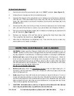
GROuNdEd tOOLS: tOOLS WItH tHREE PRONG PLuGS 

1. 

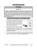
Tools marked with “Grounding Required” have a three wire cord and three prong 

grounding plug.  The plug must be connected to a 
properly grounded outlet.  If the tool should electri-
cally  malfunction  or  break  down,  grounding  pro-
vides a low resistance path to carry electricity away 
from the user, reducing the risk of electric shock.  
(See 3-Prong Plug and Outlet.)

The  grounding  prong  in  the  plug  is  connected 

2. 

through  the  green  wire  inside  the  cord  to  the 
grounding system in the tool.  The green wire in the 
cord must be the only wire connected to the tool’s 
grounding system and must never be attached to an electrically “live” terminal.  

(See 

3-Prong Plug and Outlet.)

Your tool must be plugged into an appropriate outlet, properly installed and grounded 

3. 

in accordance with all codes and ordinances.  The plug and outlet should look like 
those in the following illustration.  

(See 3-Prong Plug and Outlet.)

3-Prong Plug and Outlet

Summary of Contents for CENTRAL PNEUMATIC 95499

Page 1: ...our website at http www harborfreight com To prevent serious injury read and understand all warnings and instructions before use Copyright 2007 by Harbor Freight Tools All rights reserved No portion o...

Page 2: ...enance and cleaning procedures parts list and assembly diagram Keep your invoice with this manual Write the invoice number on the inside of the front cover Keep this manual and invoice in a safe and d...

Page 3: ...ter control of the air tool in unexpected situations Use safety equipment Always wear eye protection 6 Always wear ANSI approved safety impact glasses and hearing protection under a full face shield d...

Page 4: ...ble in line safety and alarm equip ment not included This additional equipment is necessary to properly filter and purify the air to meet minimal specifications for Grade D breathing as described in C...

Page 5: ...unattended when it is plugged in and running 14 Turn off the Compressor and unplug the unit before leaving Do not allow children and other unauthorized people to handle or play with 15 the Air Compres...

Page 6: ...g Required have a three wire cord and three prong grounding plug The plug must be connected to a properly grounded outlet If the tool should electri cally malfunction or break down grounding pro vides...

Page 7: ...boratories Inc V Volts Alternating Current A Amperes n0 xxxx min No Load Revolutions per Minute RPM UNPACKING When unpacking check to make sure all the parts shown on the Parts List on page 13 are inc...

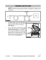
Page 8: ...r tools and equipment it is recommended that you install an oiler and water filter in line with the Air Outlet Valve 67 of the Air Compressor See Figure C Prior to using the Air Compressor the unit 3...

Page 9: ...SIGHT GLASS 21 OIL BREATHER CAP 24 FIGURE E Desired Level 2 To do so unscrew and remove the Oil Breather Cap 24 Pour approximately 1 2 quart of compressor oil into the Oil Breather Cap hole Do not ov...

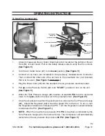
Page 10: ...ic tool not included that is to be used See Figure F next page Plug the Power Cord 55 into the nearest 120 volt grounded electrical outlet 4 Pull 5 up on the Pressure Switch 63 to its START position t...

Page 11: ...Switch 63 of the Air Compressor is in its STOP position and the unit is unplugged from its electrical outlet before perform ing any inspection maintenance or cleaning procedures or leaving it unattend...

Page 12: ...e 1 Compressor overheated 2 Restricted oil breather cap 3 Drain crankcase and refill to proper level on 1 sight glass Reduce air pressure regulation 2 Clean or replace oil breather cap 3 Pressure swit...

Page 13: ...and 19 Crankcase Gasket 20 Crankcase Cover 21 Oil Sight Glass 22 Hex Head Screw 23 Pan Head Screw M6 x 14 Part Description 24 Oil Breather Cap 25 Spring Washer 8 26 Washer 8 27 Screw M8 x 20 28 Connec...

Page 14: ...ecial or consequential damages arising from the use of our product Some states do not allow the exclusion or limitation of incidental or consequential damages so the above limitation of exclusion may...

Reviews: