background image

SKU 99637 

For technical questions, please call 1-800-444-3353. 

Page 16

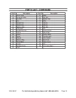
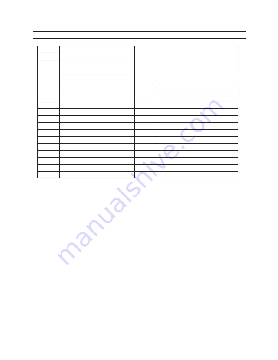
PARTS LIST - CONTINUED

Part #

Description

Part #

Description

75

Driver Guide

93

Plate

76

Connecting Plate

94

Hex Bolt

77

Hex Bolt

95

Bottom Plate

78

Nut

96

Plate

79

Spring Plate

97

Washer

80

Spring Plate

98

Washer

81

Retainer Ring

99

Hex Bolt

82

Fixing Seat

100

Pin

83

Cylinder Bushing

101

Pusher Spring

84

O-Ring

102

Idler Wheel

85

Piston

103

Spring Holder

86

Spring

104

Canister Latch

87

Stopper

105

Cap Canister

88

Retainer Ring

106

Bent Plate

89

Driver Blade

107

Upper Cover

90

Pusher

108

Pin

91

Cylinder Shelter

109

Connecting Block

92

Plate

Summary of Contents for PLASTIC CAP STAPLER 99637

Page 1: ...ved No portion of this manual or any artwork contained herein may be reproduced in any shape or form without the express written consent of Harbor Freight Tools Diagrams within this manual may not be...

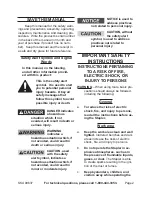
Page 2: ...in death or serious injury CAUTION used with the safety alert symbol indicates a hazardous situation which if not avoided could result in minor or moderate injury NOTICE is used to address practices...

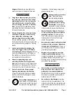
Page 3: ...balance enables better control of the Stapler in unex pected situations f Use safety equipment A dust mask non skid safety shoes and a hard hat must be used for the applicable conditions Wear heavy du...

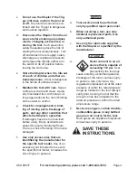
Page 4: ...on If damaged have the tool serviced before using Many accidents are caused by poorly maintained tools There is a risk of bursting if the tool is damaged h Use only accessories that are identified by...

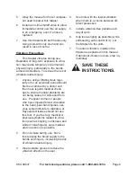
Page 5: ...WARNING Some dust created by power sanding sawing grinding drill ing and other construction activities contains chemicals known to the State of California to cause cancer birth defects or other repro...

Page 6: ...problems are not being caused or worsened from use Pregnant women or people who have impaired blood circulation to the hand past hand injuries ner vous system disorders diabetes or Raynaud s Disease s...

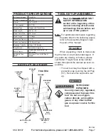
Page 7: ...ISTER 105 EXHAUST CAP 1 MAGAZINES A B 67 73 TOOL SET UP ASSEMBLY Read the ENTIRE IMPORTANT SAFETY INFORMATION section at the beginning of this manual including all text under subheadings therein befor...

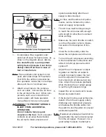
Page 8: ...ce can be hindered by under sized air supply components 3 The air hose must be long enough to reach the work area with enough extra length to allow free movement while working 4 Make sure the tool s t...

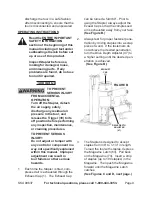
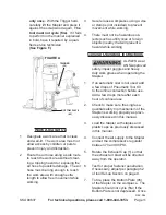
Page 9: ...ny control or component in a way not specifically explained within this manual Improper adjustment can result in tool failure or other serious hazards 1 Each time the Stapler is fired com pressed air...

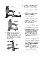
Page 10: ...the Trigger 39 moves freely without sticking Connect the air supply to the Sta pler Set the compressor s regula tor at the recommended 70 to 90 operating pressure PSI Do not exceed the maximum 90 PSI...

Page 11: ...hazardous ob jects such as utility lines or foreign objects nearby that will present a hazard while working General Operating Instructions ALWAYS wear ANSI approved safety impact goggles and heavy du...

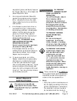
Page 12: ...loth and apply a thin coat of tool oil Then store the tool indoors out of children s reach MAINTENANCE INSTRUCTIONS Procedures not specifically explained in this manual must be performed only by a qua...

Page 13: ...med inside the Magazine 73 depress the Maga zine Latch 63 Pull back on the Magazine Use pliers to remove the jammed staple Then push the Magazine forward until the Magazine Latch catches If the plasti...

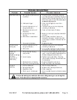
Page 14: ...Set Up Air Supply 7 Replace all vanes Housing heats during use 1 Incorrect lubrication or not enough lubrication 2 Worn parts 1 Lubricate using air tool oil and grease according to directions 2 Have q...

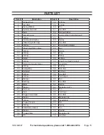
Page 15: ...Nut 12 O Ring 49 Spring 13 O Ring 50 Ring 14 O Ring 51 Safety 15 Collar 52 E Ring 16 O Ring 53 Stop Ring Depth Control 17 Piston Up Cover Driver 54 Hand Grip 18 O Ring 55 O Ring 19 Lining Ring 56 End...

Page 16: ...ate 78 Nut 96 Plate 79 Spring Plate 97 Washer 80 Spring Plate 98 Washer 81 Retainer Ring 99 Hex Bolt 82 Fixing Seat 100 Pin 83 Cylinder Bushing 101 Pusher Spring 84 O Ring 102 Idler Wheel 85 Piston 10...

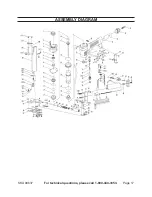
Page 17: ...SKU 99637 For technical questions please call 1 800 444 3353 Page 17 ASSEMBLY DIAGRAM...

Page 18: ...onsequential damages arising from the use of our product Some states do not allow the exclusion or limitation of incidental or consequential damages so the above limitation of exclusion may not apply...

Reviews: