background image

Page 10

For technical questions, please call 1-800-444-3353.

SKU 68739

Operating Instructions

  Read the ENTIRE IMPORTANT 

SAFETY INFORMATION section at the 

beginning of this manual including 

all text under subheadings therein 

before set up or use of this product.

Inspect tool before use, looking 

for damaged, loose, and missing 

parts.  If any problems are found, 

do not use tool until repaired.

Tool Set Up

TO PREVENT SERIOUS INJURY FROM 

ACCIDENTAL OPERATION: 

Turn off the tool, detach the air supply, safely 

discharge any residual air pressure in the tool, 

and release the trigger before performing any 

inspection, maintenance, or cleaning procedures.

TO PREVENT SERIOUS INJURY: 

Do not adjust or tamper with any control or 

component in a way not specifically explained 

within this manual.  Improper adjustment can 

result in tool failure or other serious hazards.

TO PREVENT SERIOUS INJURY: 

DO NOT USE GRINDING DISCS, GRINDING WHEELS, 

OR CUT-OFF WHEELS WITH THIS TOOL.  

This tool has no safety shield.

TO PREVENT SERIOUS INJURY: 

All accessories must be rated at 

or above 18,000 RPM.

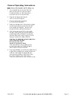
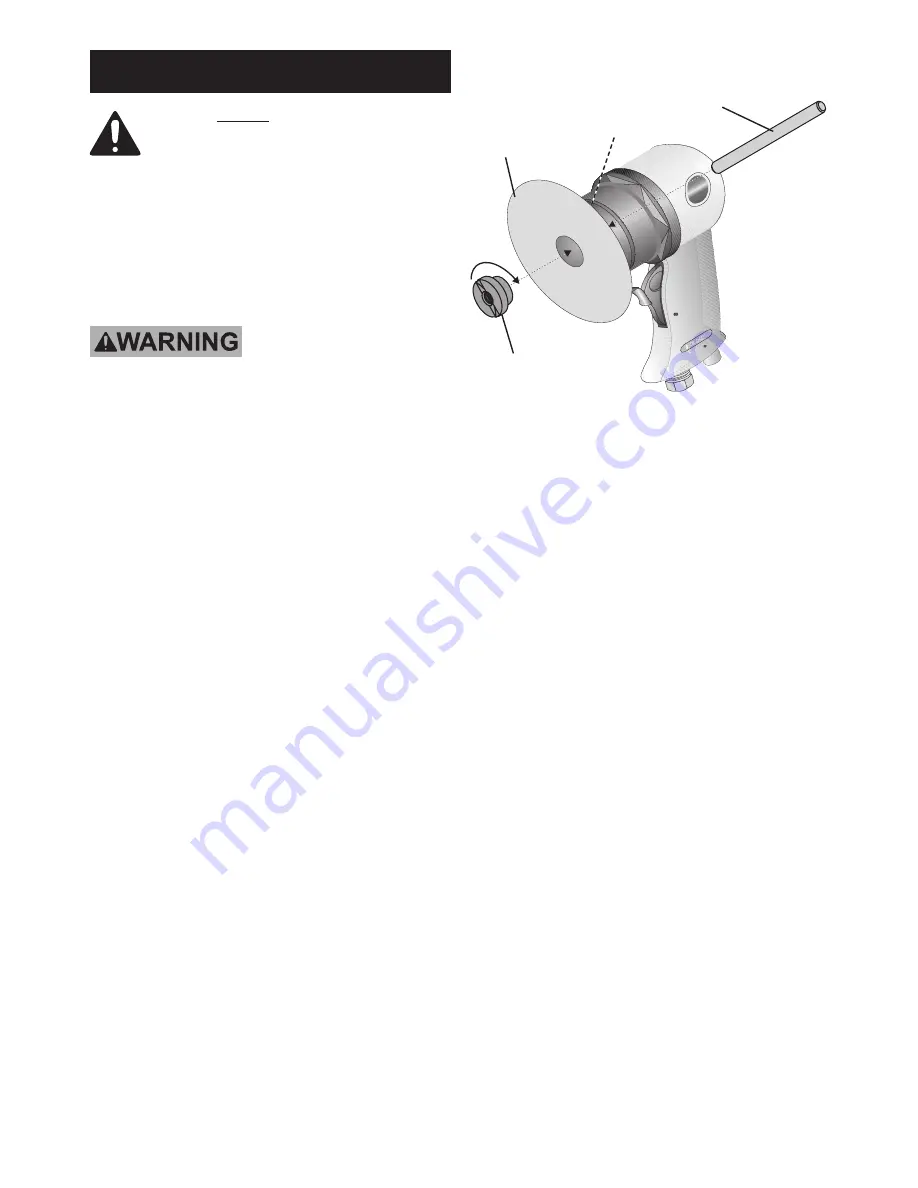
1.  Insert the Spindle Lock Pin (24) into the hole 

on the Spindle Ring (21).  See Figure D.

Spindle Lock Pin (24)

Spindle Ring (21)

Figure D:  Installing the Pad

Pad (22a/b/c)

Arbor Nut (23)

2.  Place the desired Pad (22a/b/c) onto the Spindle 

Ring.  Apply a sandpaper disc of the same size to the 

Pad with the rough side facing away from the Pad.

3.  Secure Pad in place with the Arbor Nut (23).

4.  Remove the Spindle Lock Pin before use.

Work Piece and 

Work Area Set Up

1.  Designate a work area that is clean and well-lit.  

The work area must not allow access by children 

or pets to prevent distraction and injury.

2.  Route the air hose along a safe route to reach 

the work area without creating a tripping hazard 

or exposing the air hose to possible damage.  

The air hose must be long enough to reach 

the work area with enough extra length to 

allow free movement while working.

3.  Secure loose workpieces using a vise or clamps 

(not included) to prevent movement while working.

4.  There must not be hazardous objects 

(such as utility lines or foreign objects) nearby 

that will present a hazard while working.

Summary of Contents for 68739

Page 1: ...ible Visit our website at http www harborfreight com Copyright 2011 by Harbor Freight Tools All rights reserved No portion of this manual or any artwork contained herein may be reproduced in any shape or form without the express written consent of Harbor Freight Tools Diagrams within this manual may not be drawn proportionally Due to continuing improvements actual product may differ slightly from ...

Page 2: ...asic precautions should always be followed including the following General a To reduce the risks of electric shock fire and injury to persons read all the instructions before using the tool Work Area a Keep the work area clean and well lighted Cluttered benches and dark areas increase the risks of electric shock fire and injury to persons b Do not operate the tool in explosive atmospheres such as ...

Page 3: ...t of reach of children and other untrained persons A tool is dangerous in the hands of untrained users f Maintain the tool with care Keep a cutting tool sharp and clean A properly maintained tool with sharp cutting edges reduces the risk of binding and is easier to control g Check for misalignment or binding of moving parts breakage of parts and any other condition that affects the tool s operatio...

Page 4: ... harm Some examples of these chemicals are Lead from lead based paints Crystalline silica from bricks and cement or other masonry products Arsenic and chromium from chemically treated lumber Your risk from these exposures varies depending on how often you do this type of work To reduce your exposure to these chemicals work in a well ventilated area and work with approved safety equipment such as t...

Page 5: ... hand past hand injuries nervous system disorders diabetes or Raynaud s Disease should not use this tool If you feel any symptoms related to vibration such as tingling numbness and white or blue fingers seek medical advice as soon as possible 2 Do not smoke during use Nicotine reduces the blood supply to the hands and fingers increasing the risk of vibration related injury 3 Wear suitable gloves t...

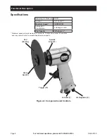
Page 6: ...t 1 4 18 NPT Maximum Speed 18 000 RPM Average Air Consumption 4 CFM 90 PSI Pad Capacity 7 8 arbor x 5 Maximum speed at stated maximum air pressure Excess air pressure is hazardous and may cause the tool to exceed stated maximum speed Air Inlet 7 Air Regulator 6 Pad 22a b c Arbor Nut 23 Trigger 12 Figure A Components and Controls Spindle Ring 21 ...

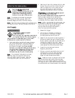
Page 7: ...ose to the air inlet of the tool Other components such as a quick connect plug and quick connect coupler will make operation more efficient but are not required WARNING TO PREVENT SERIOUS INJURY FROM ACCIDENTAL OPERATION Do not install a female quick coupler on the tool Such a coupler contains an air valve that will allow the air tool to retain pressure and operate accidentally after the air suppl...

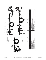
Page 8: ...r to tool B Filter Prevents dirt and condensation from damaging tool or work piece C Regulator Adjusts air pressure to tool D Lubricator optional For air tool lubrication E Coupler and Plug Provides quick connection and release F Leader Hose optional Increases coupler life G Air Cleaner Dryer optional Prevents water vapor from damaging work piece H Air Adjusting Valve optional For fine tuning airf...

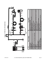
Page 9: ...E Main Air Line 3 4 minimum recommended Distributes air to branch lines F Ball Valve To drain moisture from system G Branch Air Line 1 2 minimum recommended Brings air to point of use H Air Hose Connects air to tool I Filter Prevents dirt and condensation from damaging tool or work piece J Regulator Adjusts air pressure to tool K Lubricator optional For air tool lubrication L Coupler and Plug Prov...

Page 10: ...no safety shield TO PREVENT SERIOUS INJURY All accessories must be rated at or above 18 000 RPM 1 Insert the Spindle Lock Pin 24 into the hole on the Spindle Ring 21 See Figure D Spindle Lock Pin 24 Spindle Ring 21 Figure D Installing the Pad Pad 22a b c Arbor Nut 23 2 Place the desired Pad 22a b c onto the Spindle Ring Apply a sandpaper disc of the same size to the Pad with the rough side facing ...

Page 11: ...ss the surface for best results 5 If the tool requires more force to accomplish the task verify that the tool receives sufficient unobstructed airflow CFM and increase the pressure PSI output of the regulator up to the maximum air pressure rating of this tool CAUTION TO PREVENT INJURY FROM TOOL OR ACCESSORY FAILURE Do not exceed the tool s maximum air pressure rating If the tool still does not hav...

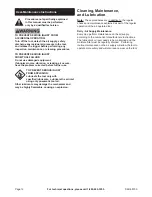
Page 12: ...fore further use TO PREVENT SEROUS INJURY FROM EXPLOSION Lubricate the tool only with specified lubricants Lubricate the air inlet using only pneumatic tool oil Other lubricants may damage the mechanism and may be highly flammable causing an explosion Cleaning Maintenance and Lubrication Note These procedures are in addition to the regular checks and maintenance explained as part of the regular op...

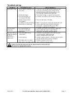
Page 13: ... Have qualified technician clean and lubricate mechanism Install in line filter in air supply as stated in Initial Set Up Air Supply Housing heats during use 1 Incorrect lubrication or not enough lubrication 2 Worn parts 1 Lubricate using air tool oil according to directions 2 Have qualified technician inspect internal mechanism and replace parts as needed Severe air leakage Slight air leakage is ...

Page 14: ... THE MANUFACTURER OR DISTRIBUTOR MAKES ANY REPRESENTATION OR WARRANTY OF ANY KIND TO THE BUYER THAT HE OR SHE IS QUALIFIED TO MAKE ANY REPAIRS TO THE PRODUCT OR THAT HE OR SHE IS QUALIFIED TO REPLACE ANY PARTS OF THE PRODUCT IN FACT THE MANUFACTURER AND OR DISTRIBUTOR EXPRESSLY STATES THAT ALL REPAIRS AND PARTS REPLACEMENTS SHOULD BE UNDERTAKEN BY CERTIFIED AND LICENSED TECHNICIANS AND NOT BY THE ...

Page 15: ...Page 15 For technical questions please call 1 800 444 3353 SKU 68739 Assembly Diagram ...

Page 16: ... the exclusion or limitation of incidental or consequential damages so the above limitation of exclusion may not apply to you THIS WARRANTY IS EXPRESSLY IN LIEU OF ALL OTHER WARRANTIES EXPRESS OR IMPLIED INCLUDING THE WARRANTIES OF MERCHANTABILITY AND FITNESS To take advantage of this warranty the product or part must be returned to us with transportation charges prepaid Proof of purchase date and...

Reviews: