background image

Page 10

For technical questions, please call 1-800-444-3353.

SKU 68064 


2. 

Quick 

Coupler

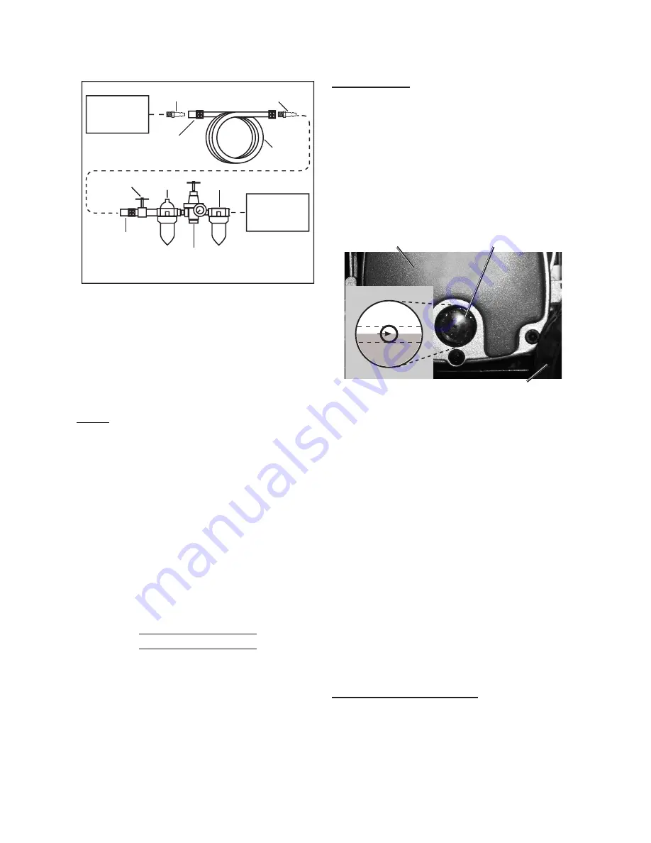
Sample Air Line Setup

Regulator with 

Pressure Gauge

Quick 

Coupler

Air Hose 

on Reel

Shut 

Off

Valve

Filter

Oiler

Coupler 

Plug

Tool

Air 

Compressor

Coupler 

Plug

Connect a regulator valve, an in-line 

shut off valve and a 1/4” NPT air hose 

(all sold separately)  to the Quick 

Coupler (84). The air hose must be 

long enough to reach the work area 

with enough extra length to allow free 

movement while working.

Note:


An in-line shutoff ball valve is an 

important safety device because it 

controls the air supply even if the 

air hose is ruptured.  The shutoff 

valve should be a ball valve 

because it can be closed quickly.

3.  Depending on the tool which you will 

be using with this compressor, you 

may need to incorporate additional 

components, such as an in-line oiler, 

a filter, or a dryer (all sold separately). 

Consult your air tool’s manual for 

needed accessories.

Checking the Oil

1.  Check the oil level before operation. 

Fill the Pump Crankcase (41) with 

approximately 5.6 oz. of premium 

quality SAE 30-weight, non-detergent 

air compressor oil. 

IMPORTANT:


Running the Air 

Compressor with the incorrect 

amount of oil will cause damage 

to the equipment and void the 

warranty. To prevent damage, 

do not use with overfilled or low 

oil. Slowly fill to full line, wait 2 

minutes and fill back up to full line. 

Compressor has small passages 

that will fill slowly.

2. 

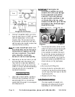
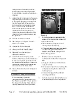
Oil Sight Glass (35)

Crankcase Cover (33)

Wheel (73)

Figure 3

OVERFILL

LOW

FULL

OIL LEVEL

The oil level should be at the center 

of the “full” level on the oil level sight 

glass, as shown in Figure 3. Add 

oil as needed to maintain this level. 

Do not let the oil level go below the 

center dot (LOW as shown above) 

and do not overfill the oil so that it is 

above the center dot (OVERFILL as 

shown above) on the sight glass.

3.  To add oil:

a. Remove the Oil Plug (39).
b. Using a funnel to avoid spills, pour 

enough oil into the Pump Crankcase 

(41) to reach the “full” level in the Oil 

Sight Glass (35).

c. Replace the Oil Plug.

Cold Weather Operation

 Premium quality 30-weight, non-

detergent air compressor oil (sold 

separately) is recommended for 

Summary of Contents for CentralPneumatic 68064

Page 1: ...ght Tools All rights reserved No portion of this manual or any artwork contained herein may be reproduced in any shape or form without the express written consent of Harbor Freight Tools Diagrams with...

Page 2: ...UNPACKING 8 INSTRUCTIONS FOR PUTTING INTO USE 8 FUNCTIONS 8 WORK PIECE AND WORK AREA SET UP 9 ASSEMBLY 9 SET UP 9 CHECKING THE OIL 10 GENERAL OPERATING INSTRUCTIONS 11 EMERGENCY DEPRESSURIZATION 12 AU...

Page 3: ...in death or serious injury CAUTION used with the safety alert symbol indicates a hazardous situation which if not avoided could result in minor or moderate injury NOTICE is used to address practices n...

Page 4: ...dequate protection Eye protection must be ANSI approved and breathing protection must be NIOSH approved for the specific hazards in the work area 4 Compressor use and care a Do not use the compressor...

Page 5: ...9 Add correct amount of compressor oil before first use and every use Operating with the incorrect amount of oil causes permanent damage and voids warranty To prevent damage do not use with overfille...

Page 6: ...maker interference or pacemaker failure 21 WARNING The brass components of this product contain lead a chemical known to the State of California to cause birth defects or other reproductive harm Calif...

Page 7: ...e equipment grounding conductor to a live terminal 4 Check with a qualified electrician or service personnel if the grounding instructions are not completely understood or if in doubt as to whether th...

Page 8: ...ad the ENTIRE IMPORTANT SAFETY INFORMATION section at the beginning of this manual including all text under subheadings therein before set up or use of this product TO PREVENT SERIOUS INJURY FROM ACCI...

Page 9: ...Bushing 76 Frame Nut 77 To attach the Wheels 73 to the frame a Slide the Washer 75 Wheel 73 and Bushing 76 onto the Bolt 74 b Slide the Bolt through the frame hole and secure in place with the Nut 77...

Page 10: ...level before operation Fill the Pump Crankcase 41 with approximately 5 6 oz of premium quality SAE 30 weight non detergent air compressor oil IMPORTANT Running the Air Compressor with the incorrect am...

Page 11: ...ight 3 Check for oil leaks and check the oil level See Checking the Oil 4 Close the in line Shutoff Valve between the compressor and the air hose 5 Make sure the air tool s throttle or switch is in th...

Page 12: ...se any built up moisture and the internal tank pressure Close the valve after moisture has drained out Do not remove the Drain Valve 18 Clean then store the Air Compressor indoors Emergency Depressuri...

Page 13: ...external surfaces of the tool with a clean cloth 3 WARNING If the supply cord of this power tool is damaged it must be replaced only by a qualified service technician Maintenance Schedule Following a...

Page 14: ...w compressor oil to the FULL level on the Oil Sight Glass 35 f Replace and tighten the Oil Plug g Discard the old oil according to local state and federal regulations Draining Moisture from the Tank T...

Page 15: ...enance Figure 8 Air Filter 2 Cylinder Head 8 Check the Air Filter 2 weekly to see if it needs replacement If working in dirty environments you may need to replace the filter more often To replace the...

Page 16: ...cally before reaching full pressure Circuit breaker trips 1 Cold weather 2 Extension cord usage 3 Engine too hot 1 Press the Reset Button then start Compressor in a heated area if temperatures drop be...

Page 17: ...il 2 Add oil to proper level check for leaks 3 Replace belt guard 4 Reduce air pressure then check all fittings with a soap solution for air leaks and tighten as needed Do not overtighten 5 Reposition...

Page 18: ...over Gasket 1 41 Crankcase 1 42 Washer 14 43 Bolt M5 x 16 10 44 Manual Overload Protector 1 45 Oil Seal 1 46 Bearing 1 47 Rotator 1 48 Bearing 1 49 Stator 1 50 Automatic Thermal Protector 1 Part Descr...

Page 19: ...Page 19 For technical questions please call 1 800 444 3353 SKU 68064 ASSEMBLY DIAGRAM...

Page 20: ...of incidental or consequential damages so the above limitation of exclusion may not apply to you THIS WARRANTY IS EXPRESSLY IN LIEU OF ALL OTHER WARRANTIES EXPRESS OR IMPLIED INCLUDING THE WARRANTIES...

Reviews: