background image

GB

Installation

Canalisation (if available)

Before you connect the auxiliary pipes for the canalisation
of the air, please check that:
• the canalisation system is according to law.
• the system does not present any obstructions.
• once  you  connect  the  stove  and  switch  on  the

auxiliary fan, there is a regular air flow at the end of the
canalisation.

• you  can  use  up  to  two  hot  air  delivery  pipes  with  a

maximum lenght of 4 m. each. If you use only one pipe,
the  maximum  lenght  is  5  m.  In  this  second  case,  the
unused outlet must be properly blocked.

• The  piping  and  conduit  must  be  protected  with  fixed,

non-reclosable  grids  or  suitable  covers.  The  minimal
section must not be reduced anyway.

• Both  the  piping  and  grids  must  be  made  of  a  material

able to carry hot air up to a maximum temperature of
80°C.

• Every device must have its own flue with a

diameter equal to or larger than the stove’s
smoke clearing tube and a height not less
than that declared.

• Never use two stoves, a chimney and a stove,

a stove and a wood kitchen, etc in the same
environment, since the draught of one could
damage the draught of the other.

• Collective  type  ventilation  ducts  that  can

lower the atmospheric pressure in the
installation environment are not permitted,
even if installed in environments that are
adjacent to and communicating with the
locale of the installation.

• It  is  forbidden  to  make  fixed  or  mobile

openings in the flue to connect devices
different from that for which it is originally
intended.

• It  is  forbidden  to  pass  other  air  feeding

channels or tubes for electrical system usage
through the flue, even if oversized.

• It is advisable that the flue be furnished with

a chamber which collects solid material and
eventual condensation situated below the
vertical entrance to the flue so that it is easily
opened and inspected through the air-tight
door.

• Whenever flues with parallel exits are used it

is advisable to raise the upwind chamber by
one element.

• The chimney tube must never pass across a

combustible surface.

The Chimney Cap

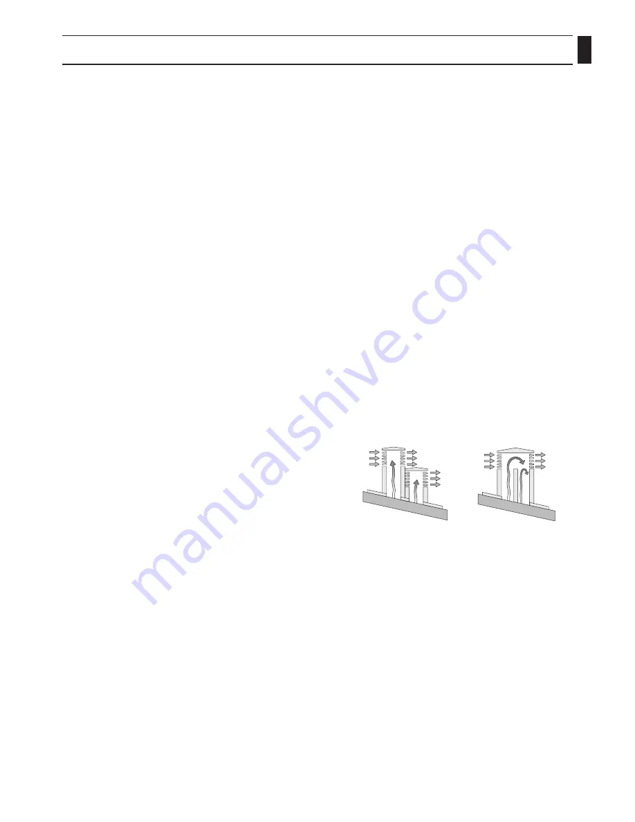
The  chimney  cap  must  respect  the  following 

requirements:

• It  must  have  the  equivalent  diameter  and

internal form of the flue.

• It must have a useful outlet diameter of not

less than double that of the flue.

• The chimney cap on the roof or that remains

in contact with the outside (for example, in 
case of open lofts or attics), must be covered 
with elements in brick or tile and must, in any 
case, be well insulated. 

• It must be constructed to prevent rain, snow,

and extraneous bodies from entering the flue 

and so that the discharge of the products of 
combustion is not inhibited by wind from 
any quarter or strength (wind-proof chimney 
cap).

• The chimney cap must be positioned in such a

way as to guarantee the adequate dispersion 
and dilution of the products of combustion 
and in any case, must be out of the reflux 
zone. This zone has different dimensions and 
forms according to the angle of inclination of 
the roof so it is necessary to adopt minimum 
heights (Fig. 2).

• The chimney cap must be a wind-proof type

and must be above the ridge.

• Eventual  structures  or  other  obstacles  that

are higher than the chimney cap must not be 
too close to the chimney cap itself.

Fig.2: characteristics of the chimney cap

YES

NO

Summary of Contents for CentroPelet ZS10

Page 1: ...let ZS10 TUZS10ENG 4 2014 HR Centrometal d o o Glavna 12 40306 Macinec Croatia tel 385 40 372 600 fax 385 40 372 611 for installation use and maintenance of pellet stove TECHNICAL INSTRUCTIONS HEATING TECHNIQUE ...

Page 2: ...ance Centre The continued use of the device in said conditions can cause fires or flashes If you do not use the auxiliary air outlet only for models with canalisation check that the fan speed is set on zero deactivated WARNING During the stove installation operation keep children out of the work area to avoid unforeseen accidents Do not block or cover in any way the body of the stove or obstruct t...

Page 3: ...intenance Failure to observe the instructions contained in the manuals Use in non conformity with the safety directives Installation in non conformity with the norms in force in the country Installation by unqualified or untrained personnel Modifications and repairs not authorized by the manufacturer Use of non original replacement parts Exceptional events Use of pellets not approved by the manufa...

Page 4: ... feeding channels or tubes for electrical system usage through the flue even if oversized It is advisable that the flue be furnished with a chamber which collects solid material and eventual condensation situated below the vertical entrance to the flue so that it is easily opened and inspected through the air tight door Whenever flues with parallel exits are used it is advisable to raise the upwin...

Page 5: ... and an environmental well being Be sure that the room where the stove is installed has sufficient aeration and if necessary install an air intake duct with a minimum recommended diameter of 50 mm to bring in air from the outside The external air intake must communicate with the stove and positioned so that it is not obstructed It must be protected with a permanent non closable grill or other suit...

Page 6: ...per campi di dimensioni nominali secondo UNI ISO 2768 Designa zione Denominazione da 0 5 fino 3 oltre 3 fino 6 oltre 6 fino 30 oltre 30 fino 120 oltre 120 fino 400 oltre 400 fino 1000 oltre 1000 fino 2000 oltre 2000 fino 4000 1 1 1 30 3 0 30 0 30 1 2 0 20 0 20 0 30 1 0 10 0 10 0 15 0 30 0 5 0 5 0 10 0 20 fine media grossolana molto grossolana Scostamenti limite in funzione dei campi di lunghezza i...

Page 7: ...ction is obligatory if the cable issued with the stove is not long enough to reach the closet socket use an extension cable along the floor Fire Safety Distance The stove must be installed respecting the following safety conditions Minimum distance from the sides and the back must be 40 cm from moderately inflammable material Easily inflammable material must not be place closer than 80 cm in front...

Page 8: ...rect and safe placement of the air intake all the measures and prescriptions Fig 7 must be respected There are distances to respect to prevent the comburant air from being subtracted from another source for example the opening of a window could cause eddies in the outside air subtracting it from the stove Fig 7 distance from walls 5 cm ...

Page 9: ...y connect the pellet stove to the flue Fill the tank with 6mm diameter pellets Open the door and check that the basket is properly inserted in its slot and that the flame trap is located in the upper part of the combustion chamber Close the door Never open the door while the pellet stove is operating Connect the stove to an outlet with the appropriate cable received with the stove Place the switch...

Page 10: ... the residual smoke Pictures are indicative and can differ from the original product Pictures are an example to understand how the product works Operations to be performed by the Authorized Assistance Centre every season before the lighting A general cleaning inside and outside A careful cleaning of the exchange tubes A careful cleaning and disincrustation of the crucible and the relative cavity C...

Page 11: ...GB Notes ...

Page 12: ...ors or error made in transcription and all figures and diagrams are for explanatory purposes only and relevant adjustment have to be made at the spot In any case it reserves the right to modify its products as deemed to be required and useful without any prior notification HEATING TECHNIQUE ...

Reviews: