5 - 9
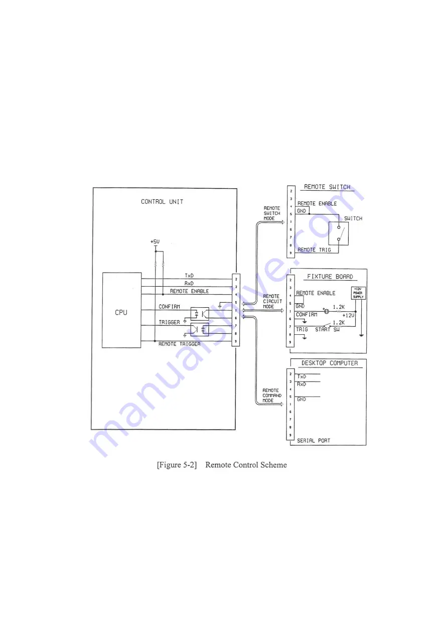
5-5. Fixtures for Remote Mode Control
To operate the machine in one of three remote modes, a fixture should be prepared by
users. Refer to [Figure 5-2] below.
The diagram is a conceptual drawing to give users technical understanding concerning
interfaces between the machine and the fixture to be designed. Users shall prepare the
fixtures in accordance with own specific needs and application.
Summary of Contents for MS930A
Page 7: ...1 2...
Page 10: ...2 1 2 Appearance and Function 2 1 Control Unit MS950A E shown...
Page 13: ...2 4 2 2 Segmentation Unit MS950A E shown...
Page 16: ...3 2 Figure 3 1 Overall System Block Diagram...
Page 30: ...5 4...
Page 31: ...5 5 Figure 5 1 Troubleshooting Flow Chart Page 2 3...
Page 32: ...5 6 Figure 5 1 Troubleshooting Flow Chart Page 3 3...
Page 40: ...6 1 6 Schematic Diagram Figure 6 1 System wiring diagram...
Page 41: ...6 2...
Page 42: ...6 3...
Page 44: ...7 2...
Page 45: ...7 3...
Page 46: ...7 4...
Page 47: ...7 5...
Page 48: ...7 6...
Page 49: ...7 7...
Page 50: ...7 8...
Page 51: ...7 9...
Page 53: ...8 2...
Page 54: ...8 3...


