page 16
www.centsys.com
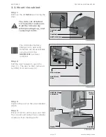
FIGURE 17
3.4.2. Leveling the boom pole
Step 1
Using the manual override, move the
boom pole to the lowered position.
Step 2
If the pole is not horizontal,
loosen both lock nuts on the
adjustment link using 2x 17mm
spanners (Figure 17).
Step 3
Adjust the adjustment link to achieve
a level boom. Use a spirit level on
the boom pole, then tighten the lock
nuts using 2x 17mm spanners.
Drive arm
Adjustment
lock nuts
(1x LH, 1x RH)
Output
shaft plate
Adjustment
link
Mechanical crushing
may occur
Figure 17 shows a right-hand configuration. Although the left-hand configuration
looks different, the levelling procedure remains the same.
PHYSICAL INSTALLATION
SECTION 3
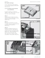
FIGURE 18
FIGURE 19
3.4.3. Coarse adjustment of the
spring tension
The spring tension is adjusted at the
factory. Should the spring tension
need to be adjusted, follow the steps
below.
Step 5
Manually override the boom pole so
that it rests under the tension of the
spring.
Step 6
Use a 24mm socket (4.5m and
6m boom) or a 17mm socket (3m
boom) to adjust the spring so that
the boom pole rests at an angle of
approximately
45˚.
The optimal
position will be determined by the
electronics when the unit is set up.
Tension
bar nut
Ratchet
spanner
Summary of Contents for SECTOR II
Page 82: ...page 82 www centsys com Notes...
Page 83: ...page 83 www centsys com Notes...


