page 37
www.centsys.com
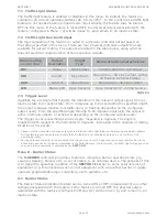
9.1 TVI Output Status
The TVI Output feature can be turned ON or OFF, independent of any other settings
associated with the feature. The TVI Output feature is turned off by default. If the feature
is turned OFF, the physical output associated with the feature (configured in 9.2) will be
driven to, and remain in, an inactive state.
9.2 TVI Function Output
The NMI input will react differently depending on whether the TVI feature is
enabled or not. The NMI input will react as follows;
If the TVI feature is Enabled, the barrier will only activate when the NMI input
is released, that is, when the NMI input is connected to COM via a switching
circuit, the barrier will only activate when the switching circuit opens.
If the TVI feature is Disabled, the barrier will activate when the NMI input is
activated, that is, when the NMI input is connected to COM via a switching
circuit, the barrier will activate as the switching circuit closes.
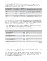
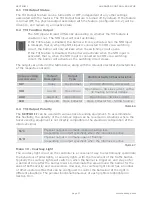
The outputs are listed in the table below, along with the relevant electrical characteristics
of the respective outputs:
9.3 TVI Output Polarity
The
SECTOR II
can be used with various ticket vending equipment. To accommodate
this flexibility, the polarity of the interlock signal can be reversed in situations where the
ticket vending equipment is not directly compatible in the standard configuration of the
interlock signal.
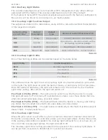
Menu 10 - Courtesy Light
The courtesy light circuit on the controller is a convenient way to electronically coordinate
the behaviour of pillar lights, or security lights, with the movement of the traffic barrier.
Typically the courtesy lights will switch on when the barrier is triggered, and stay on for
a period of time after the barrier lowers to illuminate the area around the barrier for the
sake of both security and convenience. However, the courtesy light circuit has a number
of other useful profiles that can be configured to control the behaviour of the light in
different situations. The general functional behaviour of each profile is highlighted in
Section 10.3.
TABLE 6
Output setting
on controller
Output
Description
Output
Type
Electrical Switch Characteristics
RLY
Relay
Dry Contact
24V DC/250V AC, 2A contact
XIO
Aux IO
Open Drain
Open Drain – 3A sink current, with a
3V floating terminal Voltage.
AUX
Aux Out
Open Drain
Open Drain – 3A sink current
LED
Status LED
Open Collector
Open Collector 5V – 50mA Source
N/C
Physical output is normally-closed or active low
(depending on output specified) when the interlock is active
N/O
Physical output is normally-open or floating
(depending on output specified) when the interlock is active.
TABLE 7
ADVANCED CONTROLLER SETUP
SECTION 7
Summary of Contents for SECTOR II
Page 82: ...page 82 www centsys com Notes...
Page 83: ...page 83 www centsys com Notes...


