page 48
www.centsys.com
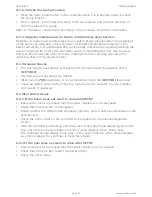
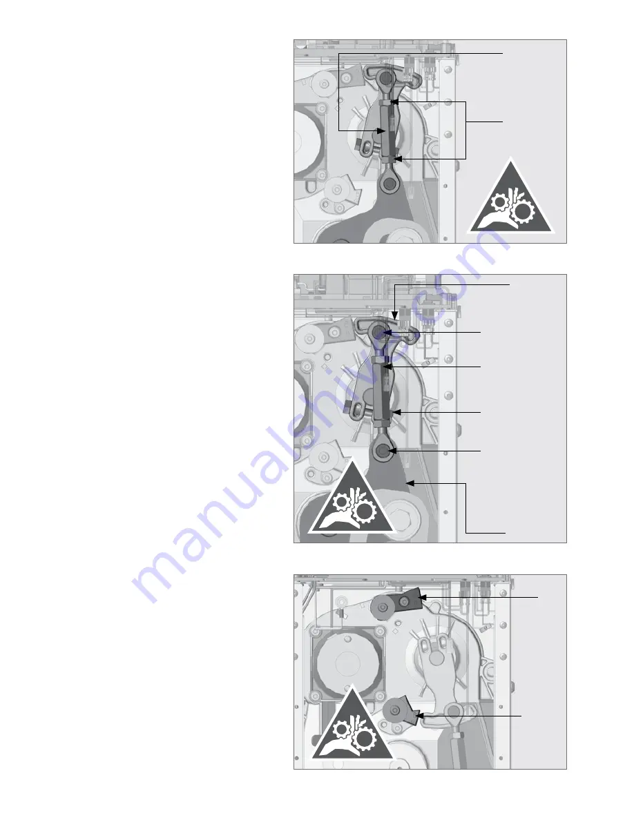
FIGURE 38
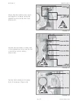
FIGURE 37
Drive arm
Adjustment link
Torque to 45Nm
Torque to 45Nm
Torque to 45Nm
Output
shaft plate
SECTION 8
Tighten the two bolts on either side
on the Adjustment Link, and the nut
on the Drive Arm to 45Nm
(Figure 38).
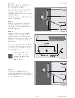
Tighten both endstops or replace
them if necessary (Figure 39).
Check that the barrier pole is level
and adjust if necessary using the
adjustment link and its lock nuts
(Figure 37).
FIGURE 39
Top
Bottom
Adjustment
lock nuts
(1x LH, 1x RH)
Adjustment
link
MAINTENANCE
Summary of Contents for SECTOR II
Page 82: ...page 82 www centsys com Notes...
Page 83: ...page 83 www centsys com Notes...

