page 51
www.centsys.com
9.1. Diagnostics
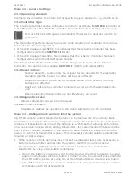
The following diagnostics enable analysis of why the unit is not performing as expected.
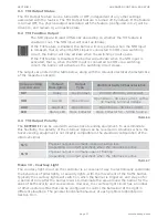
Diagnostic LEDs
The
S-SERIES
controller has a series of diagnostic LEDs which indicate the state of the
inputs. Normally-open inputs are indicated by a red LED, and normally-closed inputs by
a green LED. An illuminated red LED indicates that the signal is present
(e.g. barrier-raise pressed), while a non-illuminated green LED indicates that the signal is
absent (i.e. IRB broken)
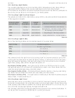
SECTOR II traffic barrier status LED
ILP
Green
on
When the inductive loop detector
output is not activated
Aux
input
Green
on
When the Aux input is not activated
Lck/
Stp
Green
on
When the Lck/Stp input is not
activated
MI
Red
on
When the memory input signal is
present
NMI
Red
on
When the non-memory input signal
is present
Raise
Red
on
When a Barrier Raise signal is
present
Lower
Red
on
When a Barrier Lower signal is
present
Status
Red
on
This LED indicates the status of the
barrier as per the table below
Off
Barrier is lowered
On
Barrier is partially or fully raised
Continuous slow flash
Barrier is raising
Continuous fast flash
Barrier is lowering
One flash every two seconds
Pillar-Light override is activated
Two flashes every two seconds
No mains present
Three flashes every two seconds
Battery voltage is low
Four flashes every two seconds
Multiple collisions have occurred
FIGURE 39
TABLE 10
TABLE 11
TROUBLESHOOTING
SECTION 9
9. Troubleshooting
Summary of Contents for SECTOR II
Page 82: ...page 82 www centsys com Notes...
Page 83: ...page 83 www centsys com Notes...

