page 58
www.centsys.com
Reconfiguring the output shaft
plate
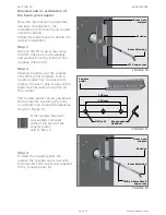
Step 3
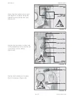
With the spring out of the way,
use the 24mm socket and ratchet
combination to loosen the spring bolt
(Figure 45). This is held in place by
a thread-locking adhesive and will
require some considerable force to
undo.
When unscrewing the
spring bolt the output shaft
plate will rotate in an anti-
clockwise direction before
locking into position.
From this point it is
possible to unscrew the bolt
completely.
Step 4
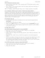
Move the spring bolt and washers to
the left-hand spring bolt position on
the output shaft plate.
Use Loctite 290 (green thread
locker) on the bolt-threads and use
a torque wrench to tighten it to
45Nm. (See Figure 46 to see the
new bolt position). The unit is now
ready for the spring assembly to be
re-installed.
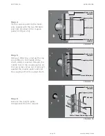
Ensure that the spring
orientation is correct before
inserting the spring back
into the cabinet.
Figures 48 and 49 depict
the correct and incorrect
spring orientations.
Step 5
Insert the spring assembly back
into the cabinet (Figure 47), making
sure that the orientation is correct
according to Figure 49, and that the
taper roller slides into the groove
of the spring support bracket at the
bottom of the cabinet as you hook
the spring onto the bolt.
FIGURE 45
FIGURE 46
FIGURE 47
Spring
assembly
Spring
bolt
Spring
bolt
assembly
Output shaft
plate
Output shaft
plate
APPENDICES
SECTION 10
Summary of Contents for SECTOR II
Page 82: ...page 82 www centsys com Notes...
Page 83: ...page 83 www centsys com Notes...


