page 60
www.centsys.com
Removal and re-orientation of
the boom pole coupler
Once the internal spring assembly
has been reconfigured, the
orientation of the boom pole coupler
needs to change.
Follow the steps below to obtain the
correct orientation:
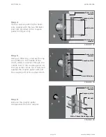
Step 1
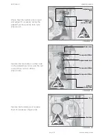
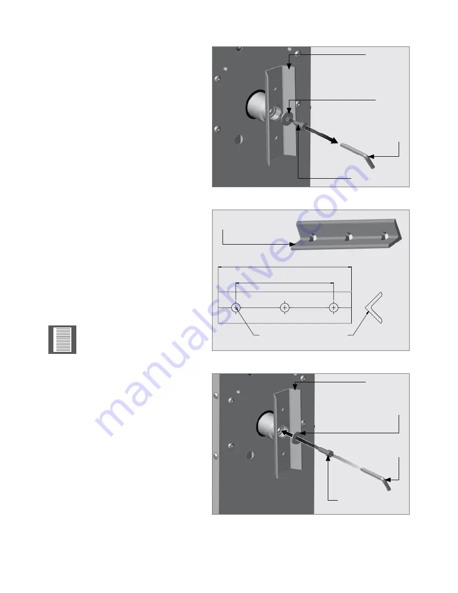
Remove the M10 cap screw using
an 8mm Allen key (not supplied)
and washer from the inside of the
coupling (Figure 50).
Step 2
Attempt to gently tap the coupler
off. If this is not possible, then a
coupler-puller may be required to
remove the boom pole coupler if the
taper lock has locked in tightly on
the coupler.
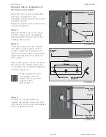
The coupler-puller can be purchased
from Centurion Systems (Pty) Ltd,
or a similar one can be fabricated as
shown in Figure 51.
If the coupler has been
successfully removed
without the need of the
coupler puller,
skip to Step 7.
Step 3
If using the coupler-puller kit,
replace the original cap screw with
the black M10x35 cap screw supplied
in the coupler-puller kit.
FIGURE 50
FIGURE 51
FIGURE 52
150mm
110mm
Ø10 (x3)
Steel angle
25x25x4
Boom pole
coupler
Coupler
puller
Washer
8mm Allen key
M10 cap screw
Boom pole
coupler
Washer
8mm Allen key
M10 x 35mm Black
cap screw
APPENDICES
SECTION 10
Summary of Contents for SECTOR II
Page 82: ...page 82 www centsys com Notes...
Page 83: ...page 83 www centsys com Notes...

