page 66
www.centsys.com
10.4. Appendix 4. FLUX 11-Pin loop detector installation
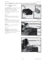
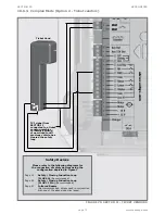
10.4.1 Single 11-pin loop
detector
The
SECTOR II
is suited for use with
different loop detector types,
including 11-pin loop detector
modules. The 11-pin base unit
screws down through the tray, into
the chassis.
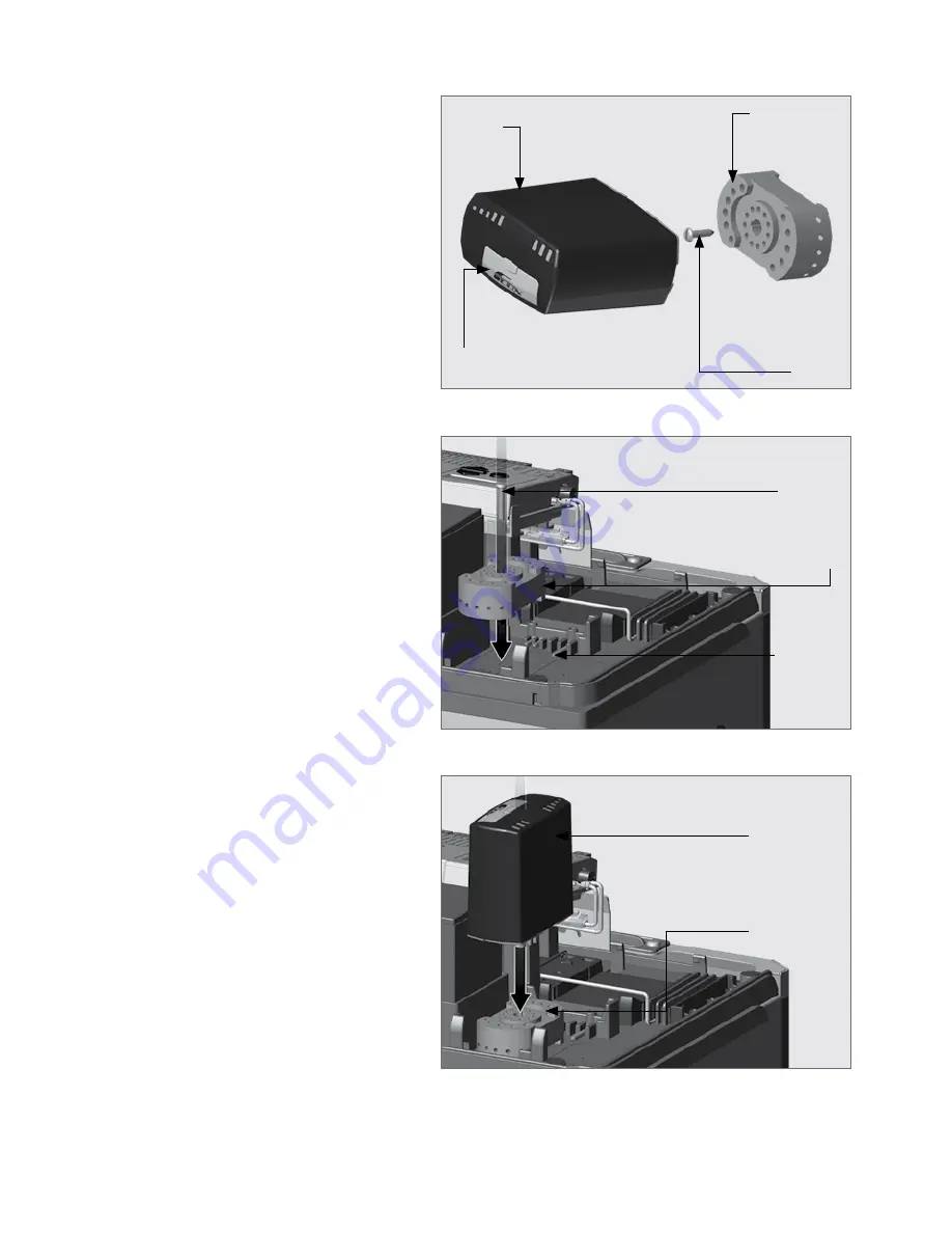
Step 1
Screw the 11-pin base onto the
electronics tray (Figure 67 and 68).
Step 2
Run the TWISTED loop wires up the
inside of the enclosure through the
wiring clips to the FLUX 11-pin unit.
Step 3
Wire the loop wires into the FLUX
11-pin unit.
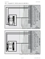
Step 4
Wire the FLUX 11-pin into the
S-SERIES
controller using the
supplied loop wire harness, following
the wiring diagram shown in
Figure 69.
FIGURE 66
FIGURE 67
FIGURE 68
DIP switch
access cover
FLUX 11-pin
base
(not supplied)
FLUX 11-pin
base
FLUX 11-pin
base
FLUX 11-pin
Screw
FLUX 11
screw
FLUX
11-pin
FLUX 11
screws
APPENDICES
SECTION 10
Summary of Contents for SECTOR II
Page 82: ...page 82 www centsys com Notes...
Page 83: ...page 83 www centsys com Notes...


