page 68
www.centsys.com
10.4.2 Dual 11-pin loop detector
In some operating modes, a barrier
may require two FLUX 11-pin loop
detectors. A typical application for a
double loop system is where both a
safety and a free-exit loop is required.
The following steps detail the process:
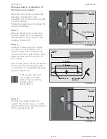
Step 1
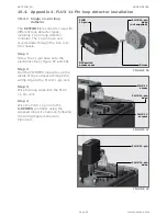
Having already installed the first
11-pin loop detector, screw the
second 11-pin base onto the
electronics tray (Figure 71 and 72).
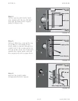
Step 2
Run the TWISTED loop wires up the
inside of the enclosure through the
wiring clips to the second FLUX 11-
pin unit. Take note of the channels
provided to separate each of the
twisted pairs for the relevant loop
detector (Figure 71).
Step 3
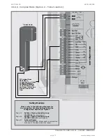
Wire the loop wires into the second
FLUX 11-pin unit.
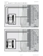
Step 4
Wire the second FLUX 11-pin into
the
S-SERIES
controller using the
supplied loop wire harness, following
the wiring diagram shown in
Figure 73.
FIGURE 70
FIGURE 71
FIGURE 72
DIP switch
access cover
FLUX 11-Pin
base
Wiring
channels
FLUX 11-Pin
base
FLUX 11-Pin
Screw
Screw
(Supplied)
FLUX
11-Pin
FLUX 11-pin
base
(not supplied)
DIP switch settings:
For the settings and descriptions,
see the pocket-guide provided with
the FLUX 11-pin.
APPENDICES
SECTION 10
Summary of Contents for SECTOR II
Page 82: ...page 82 www centsys com Notes...
Page 83: ...page 83 www centsys com Notes...


