page 71
www.centsys.com
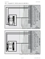
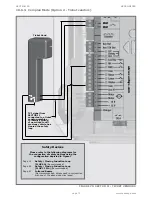
10.6. Appendix 6. Wiring diagrams for installation modes
10.6.1. Simplex Mode
These modes relate directly to the installation modes shown in Menu 4.
FIGURE 76. SECTOR II - SIMPLEX MODE
1
2
abc
3
abc
3
Efg
4
Hij
5
klm
6
nop
7
qrs
8
tuv
9
wxvz
10
*
#
1
2
abc
3
abc
3
Efg
4
Hij
5
klm
6
nop
7
qrs
8
tuv
9
wxvz
10
*
#
1
2
abc
3
abc
3
Efg
4
Hij
5
klm
6
nop
7
qrs
8
tuv
9
wxvz
10
*
#
1
2
abc
3
abc
3
Efg
4
Hij
5
klm
6
nop
7
qrs
8
tuv
9
wxvz
10
*
#
1
2
abc
3
abc
3
Efg
4
Hij
5
klm
6
nop
7
qrs
8
tuv
9
wxvz
10
*
#
OPTION 1
OPTION 2
OPTION 3
OPTION 4
OPTION 5
CENTURION
transmitter with
onboard receiver
SMARTGUARD
keypad
SOLO or Lattice
proximity access
control system
External
CENTURION
receiver
Normally-open
Pushbutton
COM
+12V
+12V
+12V
-12V
-12V
-12V
N/O
COM
N/O
COM
N/O
COM
N/O
1
2
abc
3
abc
3
Efg
4
Hij
5
klm
6
nop
7
qrs
8
tuv
9
wxvz
10
*
#
AC supply
220V AC 50HZ
Isolator
switch
Safety Devices
Please refer to the following diagrams for
the connection of safety devices using the
configuration depicted in Figure 1
Page 19
Safety / Closing Inductive Loop
(FLUX SA)
(Recommended)
Page 66
Safety / Closing Inductive Loop
(FLUX 11 Pin)
(Recommended)
Page 70
Infrared Beams
(Not recommended, unless used in conjunction
with one of the above inductive loops)
www
.centsys.com
RELAY
RELAY
APPENDICES
SECTION 10
Summary of Contents for SECTOR II
Page 82: ...page 82 www centsys com Notes...
Page 83: ...page 83 www centsys com Notes...


