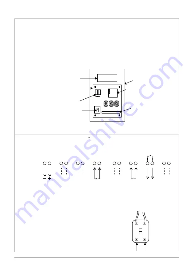
8.1 - SIMPLEX TYPE BARRIER LOGIC
8.1.1 AC MAINS SUPPLY
- Remove cover from ISOLATOR
- Connect 220V AC, 50 HZ supply
as shown.
- Refit cover to isolator
- Switch isolator to " ON "
19
19
- SIMPLEX type boom logic (Section 8.1)
- COMPLEX type boom logic (Section 8.2)
The instructions are broken down into two sections:
( See section 13 for wiring diagram )
N.B. Before doing any connections check which microprocessor
is fitted to the CP88 control card (see section 4.1).
Connections are made to the mains isolator and 16 way terminal
strip mounted on the chassis plate fitted to the door, (old version
prior Nov. 1997) or to the terminal strip inside the base.
1
16
ABBREVIATED WIRING INSTRUCTIONS
ON CHASSIS PLATE
CHASSIS PLATE
ON DOOR
TRANSFORMER
MAINS ISOLATOR
16 WAY TERMINAL
STRIP
MF
FREE EXIT
SAFETY
DOOR
TO EXISTING
WIRING
CONNECT SUPPLY
HERE
( LIVE )
BROWN
( NEUTRAL )
BLUE
8.0 ELECTRICAL CONNECTIONS
TYPICAL INPUTS FOR DOMESTIC APPLICATION BOOMDV1.X CHIP
NOTES:
1) TRIGGER INPUT FUNCTIONS AS " START - STOP - REVERSE"
2) SAFETY BEAM PREVENTS BARRIER FROM CLOSING ONTO A VEHICLE
3) 12V AUX SUPPLY CAN BE USED TO POWER SAFETY BEAMS AND RADIO RECEIVER.
12V AUX
SUPPLY
NOT
USED
TRIGGER
INPUT
NOT
USED
SAFETY
BEAM
COURTESY
LIGHT
NOT
USED
NOT
USED
3
7
9
11
13
5
1
C
O
M
C
O
M
C
O
M
M
I
IR
B
T
V
I
+
1
2
V
4
8
10
12
14
16
6
2
ON
OFF
15
CP88
CONTROL CARD
Summary of Contents for CP71
Page 2: ...2 2...
Page 4: ...4 4...
Page 7: ...7 7 4 2 DETERMINATION OF OPERATIONAL MODE...
Page 16: ...16 16...
Page 21: ...21 21...
Page 28: ...28 28...
Page 38: ...34 34 38 38...
Page 39: ...39 39...


