8
H
I.
1.
.
Battery Charger
Battery Cable Connection
Mounting The Control Box
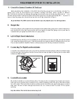
The plug-in battery charger is provided to keep the batteries charged to an optimum voltage. A red
coloured LED, located on the charger casing will illuminate to indicate that the charger has been
connected to an active power supply.
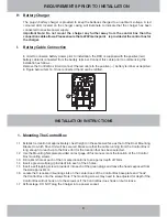
In order to conserve battery power prior to installation, the RDO is supplied with the positive (red)
battery cable disconnected from the battery terminal. Connect this cable prior to commencing the
installation as follows:-
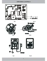
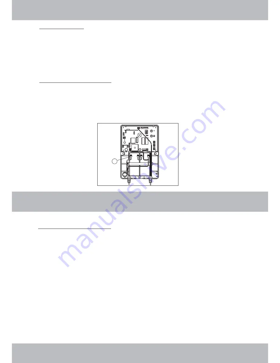
Remove the Control Box lid and connect the red cable to the positive (+) battery terminal as depicted
in Figure below Item 19. Once connected the lid can be refitted.
1.1
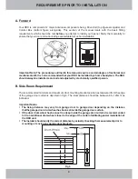
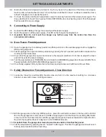
Establish a location at approximately chest height on the same wall face as that of the Door Mounting
Bracket to which Drive Unit will be secured. Make sure that the cable running from the Control Box is
long enough to reach up to the Drive Unit for the location that has been selected.
1.2
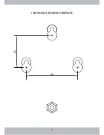
Use the Mounting Template provided on last page of this manual, mark the location of the 3 Control
Box mounting screws.
1.3
Drill a 6mm hole at each of the 3 marked locations to an approx depth of 75mm
1.4
Insert a green wall plug (provided) into each of the 3 holes
1.5
Insert a self tapping screw (provided) into each of the green plugs and leave the heads exposed from
the wall approx 6mm.
1.6
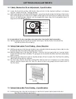
Locate the 3 recessed mounting slots on the center back of the Control Box base plate and hook
the Control Box onto the screws Note: The mounting screws may need to be adjusted for depth if the
Control Box will not hook on to the screws or if the Control Box does hook on but is loose.
1.7
At this stage, DO NOT plug the Charger into a power socket.
Important Note: Do not mount the charger any further away from the control box than the
connection cable allows. Please ensure that a 220V mains point
is provided at the control box for
the charger.
.
.
“
”
REQUIREMENTS PRIOR TO INSTALLATION
INSTALLATION INSTRUCTIONS
19

