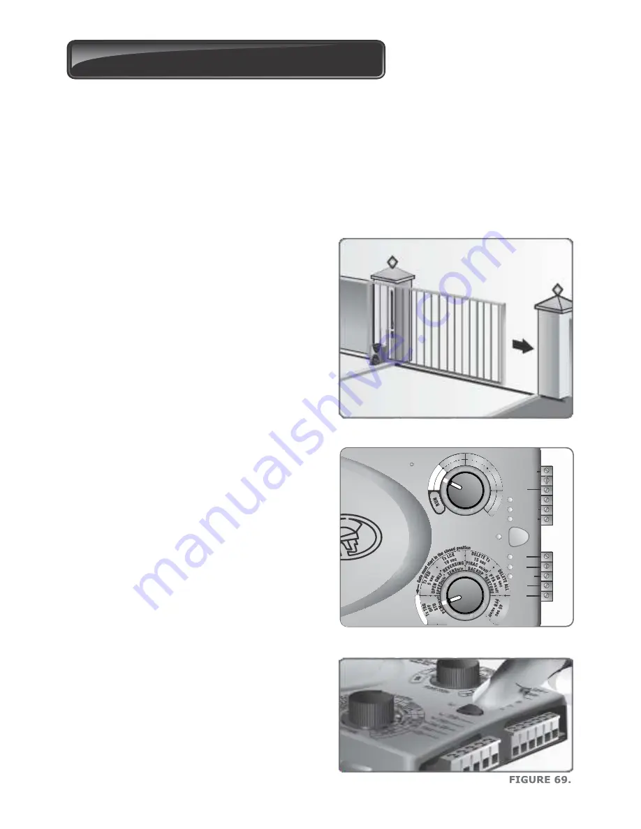
Setting up the gate Limits
FIGURE 67.
1. Ensure that the gate is in the fully closed
position and the motor drive is engaged.
2. Rotate the Function Dial to the LIMITS
position along the ‘A’ row of options.
3. Rotate the Setting Dial to the SETUP
position along the ‘A’ row of options.
FIGURE 68.
SETUP:
SETUP:
Step 1: Select FUNCTION
Step 2: Select SETTING
Step 3: Press
Step 4: When finished
select RUN
Aux 12V
Safe Com
Com
Safe OPN
Safe CLS
LCK/STP
TRG
PED
Aux I/O
Com
LED
S
TI
MI
L
S
E
T
O
M
E
R
AUTOCL
OSE
M
O
D
E
P
R
O
FIL
E
A
B
C
D
E
FUNCTION
A B C D E
SETTING
P
U T
E S
www.centsys.com
4A. Press the pushbutton to select this
feature.
page 47
20. Commissioning the System
Close
the gate
Introduction
The
D2 Turbo
and
D2 Turbo Low-Voltage
sliding gate operators’ advanced functions
are controlled by intelligent microcontroller-based electronic controllers. These systems’
features and functions are enabled and disabled using the two user-friendly setting dials,
with the top dial used for selecting the desired function, and the bottom dial used for
selecting the specific setting to be enabled or disabled.


