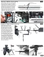
Section 5: Muffler & fuel routing
5.2
5.3
5.4
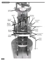
Section 6: Flybar & head assembly
6.1
5.1
Install the pressure nipple using a high temperature
adhesive (thread lock) to the top of the muffler and
the 4mm plug screw to the bottom (5.1). Bolt the
muffler to the engine (5.2) flush (no gasket required)
using thread lock. Connect fuel tube between the
fuel pickup in the tank and the carb on the engine
with as little slack as possible (5.3). Connection
between the carb and the fuel pickup tube (short
straight) should be level (keeps fuel draw rate in
inverted flight). Connect the fuel tank air tube (long
curved) to the muffler pressure nipple (5.3).
Install the flybar, flybar control arms,
weights and paddles into the rotor
head seesaw assembly as shown (6.1).
First slide the flybar in place through
the seesaw assembly. Then slide the
ball bearings included with the two ball
bearings into the seesaw cups on each
end. Then slide the M3x6 plastic spacers
on to each side of the flybar. Next slide
the 2 flybar control arms as shown
(6.1) Use thread lock on the set screws
connecting the flybar weights to the flybar
(6.2 - 6.3). Align the flybar paddles and
control arms level to the seesaw assembly
(LEADING EDGE OF PADDLES MUST
GO CLOCKWISE). The assembled flybar
must be the same length on each side of
the rotor head. Install the completed rotor
head to the main shaft (6.4) with one 3x16
cap screw and M3 locknut.
6.2
6.3
6.4
Using thread lock
M4x5 set screw (2)
Using thread lock
M3x3 set screw (2)
M3x16 socket head
cap screw (1)
M3 locknut (1)
Using thread lock:
Hardware provided with muffler
Using thread
lock:
3x25 socket
head cap
screw (2)
M3x7 Ball
bearing (2)
7
Flybar
control
arm
Flybar weight
Flybar paddle
(Optional Toki muffler for Toki .40 engine shown. Toki muffler is
supplied with a Hawk Pro “Toki engine and muffler combo”)
Leading edge
Trailing edge
M4x5 Set
screw
M3x4 Set
screw
M3x6
spacer (2)
Seesaw
assembly
(bearing cup)


