10
STEP 11 Bottom Hatch
STEP 11 Bottom Hatch
STEP 11 Bottom Hatch
STEP 11 Bottom Hatch
STEP 11 Bottom Hatch
STEP 12 Attaching the Windshields
STEP 12 Attaching the Windshields
STEP 12 Attaching the Windshields
STEP 12 Attaching the Windshields
STEP 12 Attaching the Windshields
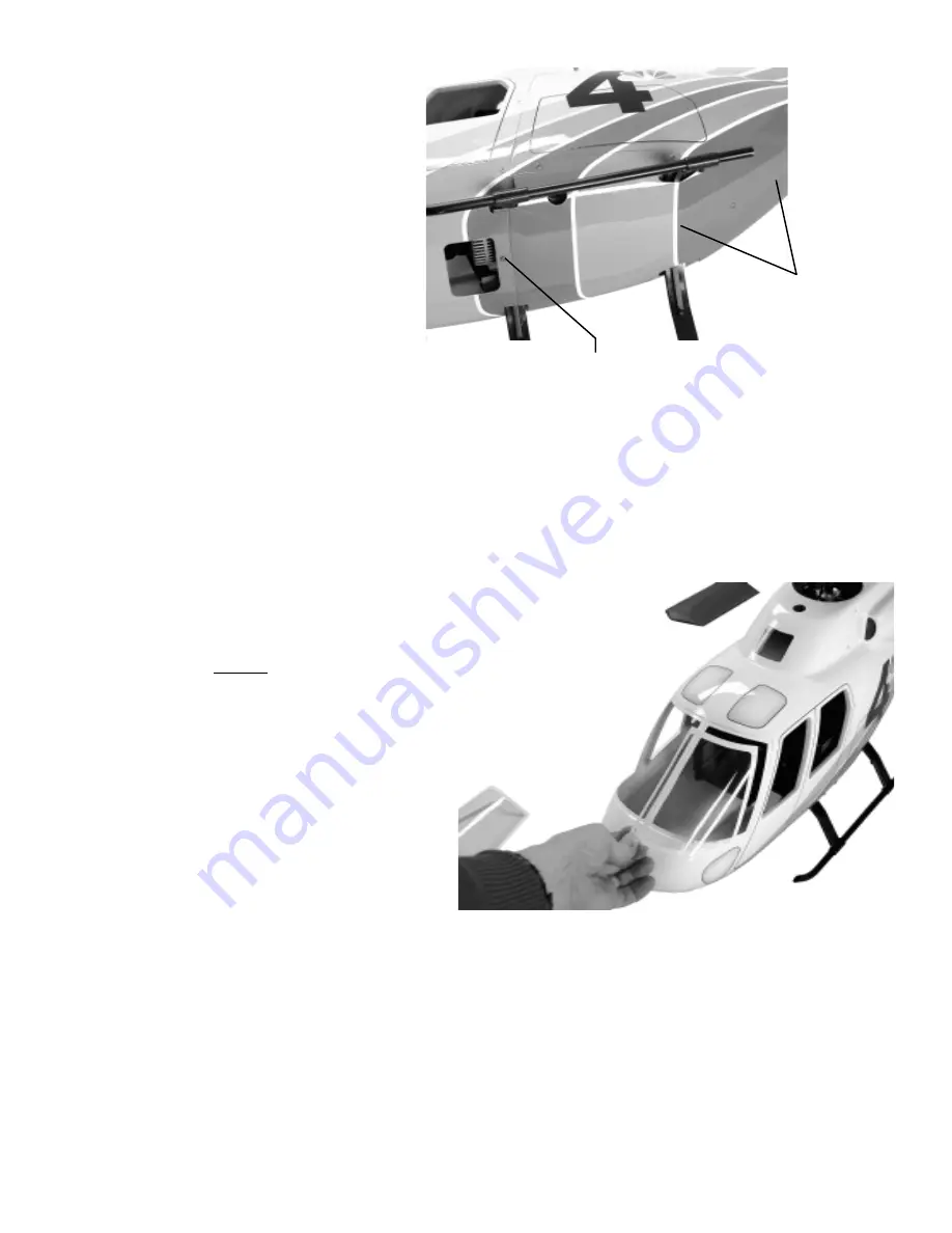
If an exhaust diverter is to be used, install
before the bottom hatch is attached. The
bottom hatch is already cut to fit the landing
gear on the scale mechanics. Start by insert-
ing the rear cutouts and gently flexing the
ears to engage the rear struts, next grasp the
hatch with both hands, fingers on the side
edges and thumbs centered at the front and
gently bend the hatch in a “U” shape to allow
the front lip of the hatch to be inserted under
the edge of the front nose. Secure the hatch
using six M3x8 Phillips Self Tapping Screws.
Rear Body
with Bottom
Hatch
(unfinished)
[CN1075-2]
M3x8 Self
Tapping
Screws x 6
[CN1075-5]
Kit
Kit
Kit
Kit
Kit V
V
V
V
Ver
er
er
er
ersion
sion
sion
sion
sion
Mark the six screw locations on the hatch with a
pencil. Using tape, attach the hatch to the rear body
and slowly drill each of the six holes using a
3/32” [2.5mm] drill bit. Remove the hatch and roughen one side of the six plywood blocks and the area around
the inside hole on the rear body. Using slow-CA bond each plywood block in place, clamp until dry. Redrill each
hole in the rear body through the plywood blocks and using one M3x8 Phillips Self Tapping screw, insert and
form the threads. After the fuselage is painted the hatch can be attached, remember to paint the screws to match the
color scheme.
Twinstar Detail Manual
Twinstar Detail Manual
Twinstar Detail Manual
Twinstar Detail Manual
Twinstar Detail Manual
Apply a thin 1/16” [1.5mm] bead of adhesive centered in the recessed
surface. Pick up the windshield by the edges only, remember “Goop” or
“Goop Fingerprints” cannot be removed if they touch a clear part.
Using single-use “Hobby grease syringes” are great and really
make this a simple task as the adhesive width and amount
can be easily controlled. Let dry for 24 hours. An
excellent alternative is to use “R/C 56 Canopy
Glue” from any airplane hobbyshop. This adhesive
remains white until fully curred in 24-48 hours
(slow but very good) but can be cleaned up using a
cloth and will not damage or scuff clear parts. When
dry, it is very strong. After bonding, apply “magic”
tape to secure the windshield halves until dry.
STEP 13 Fueling, Glow Plug Extension and Antenna Routing
STEP 13 Fueling, Glow Plug Extension and Antenna Routing
STEP 13 Fueling, Glow Plug Extension and Antenna Routing
STEP 13 Fueling, Glow Plug Extension and Antenna Routing
STEP 13 Fueling, Glow Plug Extension and Antenna Routing
If you have not already considered these items, now is the time. Most scale helicopter present new challenges to
simply change the glow plug when shrouded inside the fuselage. Century makes most items to solve these as
follows: CN2054 Universal Glow Wrench (check for compatibitity), CN2222 Remote Glow Plug Adapter -
absolutely essential for all model helicopters and CNT4444 In-line fueling valve with filter and filler - avoids
pulling the fuel line from the carburator to fuel the helicopter. The antenna wire needs to be routed in a path that
avoids the wire from touching any metal surfaces or servo wires. It is best that all the servo leads be collected and
secured on one side of the mechanics leaving the opposite side for the antenna. Whether you prefer the original
wire or use a “mini-whip” antenna, make sure that anytime the wire needs to cross any metal, use a short 1/2”
[12mm] length of fuel tubing to insulate the wire and attach with a tie wrap. Clean installations always work best.


