7
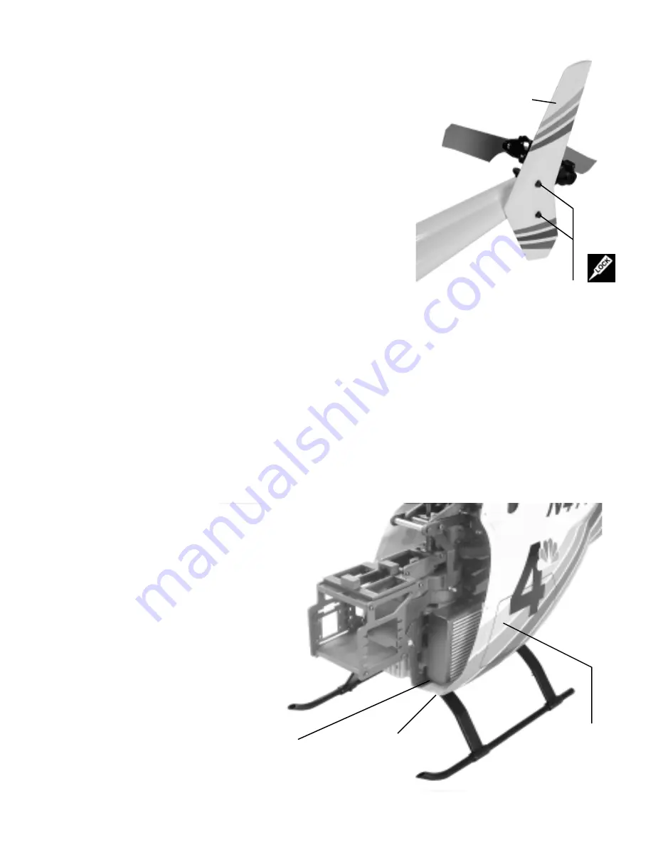
STEP 5 Vertical Tail Fin
STEP 5 Vertical Tail Fin
STEP 5 Vertical Tail Fin
STEP 5 Vertical Tail Fin
STEP 5 Vertical Tail Fin
The vertical tail fin is attached with the short portion on the bottom. Slide
one M3 Washer onto one M3x12 Socket Cap screw and insert through
the pre-drilled hole in the vertical fin, repeat for the second hole. Apply
thread lock to the exposed threads and thread into the vertical fin mounts
already installed on the tail gearbox. Be careful, tighten until snug and
then only a 1/16” of a turn more. Warning, these fasteners only hold the
fin in place, overtightening will crush the fin.
Kit
Kit
Kit
Kit
Kit V
V
V
V
Ver
er
er
er
ersion
sion
sion
sion
sion
The edges of the fin need to be sanded before the paint in applied.
After painting, the holes for the screws will need to be re-drilled to
remove any paint that accumulated in the holes.
M3x12 SHCS x 2
M3 Flat Washer x 2
[CN1075-5]
STEP 6 Landing Gear & Muffler Attachment
STEP 6 Landing Gear & Muffler Attachment
STEP 6 Landing Gear & Muffler Attachment
STEP 6 Landing Gear & Muffler Attachment
STEP 6 Landing Gear & Muffler Attachment
Vertical Fin
(unfinished)
[CN1075-3]
As there is enough space to attach the 30 size muffler after the mechanics are secured to
the landing gear, remove it for now. If you have chosen to install the 46-50 size engine, it
is very important that the muffler screws are installed loosely in the engine before the side
frames are attached, if this is not the case, do it now. Place the mechanics and the rear fuselage on top of the
assembled landing gear. Slide one M3 Flat Washer onto one M3x15 Socket Cap screw and insert from the bottom
of the front landing strut, through the fiberglass floor and the align to the front hole of the mechanics. Attach one
M3 Locknut on the inside using pliers to hold the nut while the bolt is tightened from below. Repeat for the other
side. To attach the rear strut, repeat the same procedure but tip the mechanics over the side of a table. Using a
5.5mm nut driver, place a drop of grease on the top of the locknut and insert into the nut driver (this will hold the
nut from falling out) and carefully insert the nut driver between the side of the mechanics and the fuselage. You
will need to maneuver past the angle supports but with patients and keeping the nut driver horizontal, the rear
locknuts can be secured. This can also be accomplished with the muffler installed but more patience is needed as
you are unable to see the bolt. Repeat for the other side,
this time with the fuel tank as the challenge.
It is assumed that the muffler holes have been
cut for the muffler to be installed, the edge of
the hole should be fuel proofed with a Polyure-
thane paint or simple clear nail polish to seal
the paint finish to the fiberglass. There is
enough room to use a long allen key or hex
screwdriver to access the muffler bolts. If
you have been test flying the mechanics,
clean the muffler bolts, the muffler threads
and the through holes on the engine with
rubbing alcohol before assembling. Make
an aluminum gasket if none is provided
with the muffler, after tightening the bolts,
torque an additional 1/16” of a turn.
Finally, run the pressure line back to the
fuel tank and arrange any other fuel lines
for optional filler valves or fittings.
M3
Locknut
on top.
M3x15 SHCS x 4
M3 Flat Washer x 4
M3 Locknut x 4
Rear Body with
Bottom Hatch
(unfinished)
[CN1075-2]
Twinstar Detail Manual
Twinstar Detail Manual
Twinstar Detail Manual
Twinstar Detail Manual
Twinstar Detail Manual


