29
INST
ALLA
TION
AND OPERA
TION MANUAL
BA
THTUB WITH MASSAGE SYSTEM
EN
3
HYDROMASSAGE BATHTUB - INSTALLATION
The inspection prior installation must be carried out in the following fashion:
direct all nozzles towards bathtub bottom,
fill bathtub with water to the level of 3÷4 cm above the highest nozzles,
preliminarily connect the bathtub to the power supply system complying with all safety rules,
test all functions of the equipment,
make sure all pipes and connections are watertight,
check the degree and uniformity of water jet aeration,
leave massage systems activated for 10÷15 minutes,
deactivate massage systems and drain water from the bathtub,
check the drain connection is watertight.
.
Having completed the visual inspections and tests, the bathtub must be properly installed.
NOTICE!
In order to ensure proper, long-term and failure-free operation of our product, we recommend its installation be carried out
by an authorised service centre.
As the bottom of the bathtub is fitted with elements requiring free air flow and easy access in the case of repairs/service, in-
stallation of a fixed bathtub casing is not recommended. We offer enclosures which are easy to assemble and disassemble.
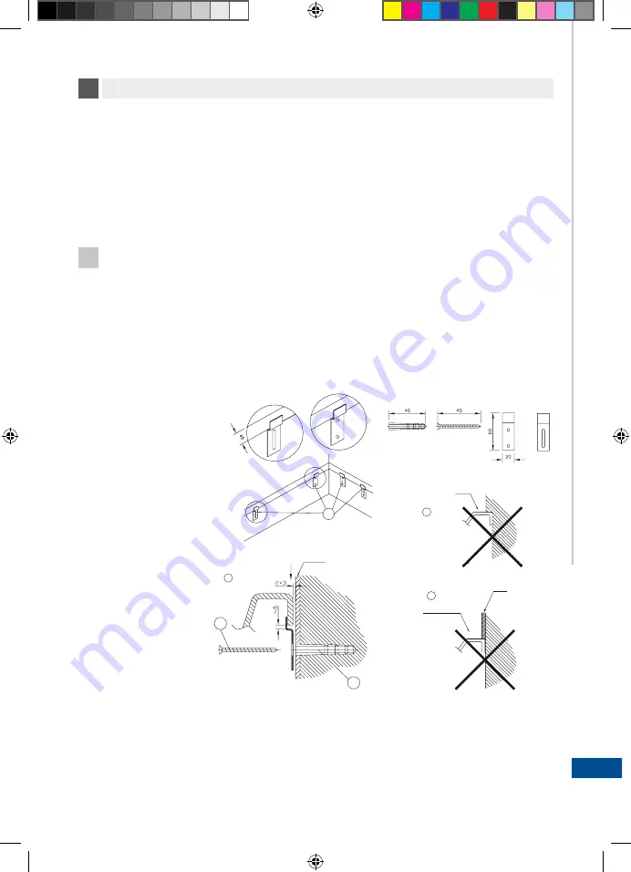
Its range includes all our models of bathtub. The bathtub must be levelled by means of adjustable feet which must be placed
on damping pads (included in the set). The bathtub must be located approximately 2 mm from the surrounding walls and the
gap must be filled with a sealing tape or sanitary silicone sealant. System operation causes small vibrations which must not
be transferred to adjacent walls. The bathtub is mounted by means of supplied handles fitted with wall anchor plugs. The
enclosure must be installed on the levelled bathtub with a gap of approximately 5 mm between the enclosure and floor in
order to ensure proper ventilation.
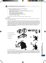
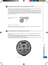
B - correctly fixed bathtub
C,D - incorrectly fixed bathtub
1 - wall anchor plug.
2 - fixing screw
3 - fixing handles
Pic.1 Bathtub installation on the wall.
If a fixed casing is necessary, it must constructed in a way that facilitates removal from the bathtub for service or maintenan-
ce purposes. The casing must be fitted with ventilation ducts made by means of, e.g. ventilation gratings. The ducts can also
function as inspection openings used for drain-overflow system connection and also for periodical visual inspections. The
bathtub must not rest on its edges but must be fully supported by its feet. The gap between the bathtub and casing must be
filled with sealing tape or sanitary silicone sealant.
•
•
•
•
•
•
•
•
•
a
a
b
B
b
1
2
3
C
D
1.
2.
3.
!
Summary of Contents for AirMATIC
Page 2: ...www cersanit com...
Page 47: ...47 INSTALLATION AND OPERATION MANUAL BATHTUB WITH MASSAGE SYSTEM EN...
Page 48: ...48 RU 1 Cersanit T 2 Ma a 3 MO T M...
Page 49: ...49 RU 3 MO 3 4 10 15 2 5 B C D 1 2 3 1 a a b B b 1 2 3 C D 1 2 3...
Page 51: ...51 4 O temp 38o C 3 3 4 3 4 cm 5 4 RU...
Page 52: ...52 5 5 1 O MENU SET RU...
Page 54: ...54 RU 5 5 2 O c 5 3 O 1 2 1 40 100...
Page 55: ...55 RU 2 3 4 5 5 4 O 1 2 1 40 100 5...
Page 56: ...56 RU 5 2 wci ni cie 3 wci ni cie 4 wci ni cie 5 wci ni cie 5 5 O 5 6 5 6 1 A 3 5...
Page 57: ...57 RU 5 6 2 O 45 1 100 2 5 6 3 1 2 5 10 a Er2 Er1...
Page 58: ...58 RU 5 6 4 1 2 3 5 6 5 5 6 6 Ko 5 Ko O Er1 Er2 Er3 Er4...
Page 59: ...59 RU 6 MICRO 5 6 1 O LED 1 M LED2 2 od MIN MAX MAX LED3...
Page 61: ...61 RU MICRO 6 3 O 1 2 1 LED4 2 20 6 4 O 6 5 O 45 6...
Page 62: ...62 RU 1 100 LED1 2 6 6 1 2 20 MICRO 6...
Page 63: ...63 RU AIRMatic 9 O 10 C 5 HYDROMatic 10 O 6 2 4 A B 7 DUOMatic 11 O 6 2 4 10 A B C 7 7...
Page 64: ...64 RU 7 EURO 6 MATIC A B C 7 MATIC DUOMATIC HYDROMATIC AIRMATIC A B C C B A C 8 O MATIC...
Page 65: ...65 RU 9 AIRMatic 7 10 HYDROMatic 11 DUOMatic...
Page 66: ...66 RU a 10 10 5 8 9 O O 800 1200 2000...
Page 67: ...67 RU...
Page 87: ...87 RO INSTRUC IUNI DE MONTAJ I NTRE INERE A C ZILOR DE BAIE CU SISTEME DE MASAJ...
Page 107: ...107...


