30
3
HYDROMASSAGE BATHTUB - INSTALLATION
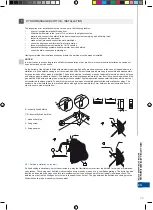
Water connections
Depending on the bathtub type and its accessories, there are different methods of filling it with water.
The easiest way is to install an incorporated washbasin tap (under plasterwork), which makes it possible to supply the
bathtub with water without interfering with its structure.
Another possibility is to install a bathtub tap with a spout. However, this kind of installation must be carried out by means of
a professional fret saw so as to avoid acrylic surface damage. The exact location of the installation is also essential. It must
be carefully chosen so that it does not interfere with the casing and will not considerably weaken the bathtub structure. If a
user makes the openings for tap installation individually, it does not change the terms of product guarantee.
Some bathtub models offer the function of filling it by means of a system of water nozzles.
In order to facilitate this function, a standard connection with a reinforced flexible line must be constructed. The line must be
connected to a special connection in the bathtub water system. The discharge pipe must be installed in a manner ensuring
it is totally watertight so that water does not leak in the vicinity of electrical elements of the system.
Electrical connections
The bathtub must be connected to the wiring system by a properly certified and authorised electrician. One of the terms of
guarantee is to confirm the conformity of the electrical connection in the guarantee card. According to applicable standards
(PN-EN 60335-1 and PN-EN 60335-2-60) a bathtub with the hydromassage function, as a Class I appliance, must have a
fixed connection to the wiring system. The bathtub electrical connection must be prepared in Zone I (connection under the
bathtub). The connection cable box must have at least IPX5 protection degree. For safety reasons, the bathtub must be
connected to a network (TN-S) fitted with a differential-current switch of maximum activation current equal to 30mA. The
switch is to be tested on its operational effectiveness at intervals recommended by the switch manufacturer. In the bath’s
permanent electric installation a device should be included that enables the circuit to be isolated at all poles in accordance
with regulations applicable to construction of the installation. The distance between contacts of all poles in the device is not
less.than.3.mm.
The electrical connection must be made by means of a wire of appropriate diameter and must also be properly protected
with regard to the maximum power input.
For example, the appliance power is equal to
1kW – S191B10 fuse and a power lead min. 3x1 mm2.
2kW – S191B16 fuse and a power lead min. 3x1,5 mm2.
3,6kW – S191B20 fuse and a power lead min. 3x2,5 mm2.
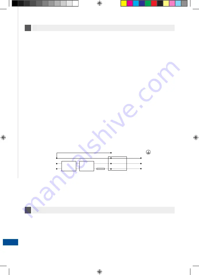
Additionally, a local equalizer connection between the metal bathtub construction and the electrical system protection lead
must be created.
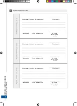
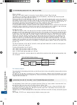
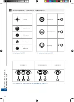
Pic.2 Connection diagram
The installer (the first hydromassage bathtub owner) should make the instruction and installation manual available to furture
owners and users.
The bathtub may be adjusted (or repaired) only by installers who have proper certifications and authorisations to be presen-
ted to appropriate regulatory bodies ensuring that they comply with local safety provisions regarding electrical safety, water
supply and waste water disposal.
4
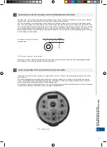
GENERAL RULES FOR USING THE HYDROMASSAGE FUNCTION
The hydromassage function can be used by any person who does not have any serious ailments connected with the circu-
latory system, heart and nervous system. If in doubt, please consult your doctor.
The massage temperature and time must be adjusted to own needs. However, one must not forget that the higher water
temperature the shorter the massage time. With water temperature equal to 38ºC the massage time must not exceed 10
minutes (36ºC – not longer than 20 minutes).
Cool baths (max. 31ºC) have an analgesic and anti-inflammatory effects and intensify the circulatory and respiratory system
activity.
Neutral baths (34÷36ºC) have a relaxing impact and alleviate increased muscle tone.
INST
ALLA
TION
AND OPERA
TION MANUAL
BA
THTUB WITH MASSAGE SYSTEM
EN
TN-S INSTALLATION (of a building)
cable box
PE
N
L
B10-B2
5
IPx5
PE
N
L
PE
N
L
Circuit
breaker.
Differential-
current
switch
Summary of Contents for AirMATIC
Page 2: ...www cersanit com...
Page 47: ...47 INSTALLATION AND OPERATION MANUAL BATHTUB WITH MASSAGE SYSTEM EN...
Page 48: ...48 RU 1 Cersanit T 2 Ma a 3 MO T M...
Page 49: ...49 RU 3 MO 3 4 10 15 2 5 B C D 1 2 3 1 a a b B b 1 2 3 C D 1 2 3...
Page 51: ...51 4 O temp 38o C 3 3 4 3 4 cm 5 4 RU...
Page 52: ...52 5 5 1 O MENU SET RU...
Page 54: ...54 RU 5 5 2 O c 5 3 O 1 2 1 40 100...
Page 55: ...55 RU 2 3 4 5 5 4 O 1 2 1 40 100 5...
Page 56: ...56 RU 5 2 wci ni cie 3 wci ni cie 4 wci ni cie 5 wci ni cie 5 5 O 5 6 5 6 1 A 3 5...
Page 57: ...57 RU 5 6 2 O 45 1 100 2 5 6 3 1 2 5 10 a Er2 Er1...
Page 58: ...58 RU 5 6 4 1 2 3 5 6 5 5 6 6 Ko 5 Ko O Er1 Er2 Er3 Er4...
Page 59: ...59 RU 6 MICRO 5 6 1 O LED 1 M LED2 2 od MIN MAX MAX LED3...
Page 61: ...61 RU MICRO 6 3 O 1 2 1 LED4 2 20 6 4 O 6 5 O 45 6...
Page 62: ...62 RU 1 100 LED1 2 6 6 1 2 20 MICRO 6...
Page 63: ...63 RU AIRMatic 9 O 10 C 5 HYDROMatic 10 O 6 2 4 A B 7 DUOMatic 11 O 6 2 4 10 A B C 7 7...
Page 64: ...64 RU 7 EURO 6 MATIC A B C 7 MATIC DUOMATIC HYDROMATIC AIRMATIC A B C C B A C 8 O MATIC...
Page 65: ...65 RU 9 AIRMatic 7 10 HYDROMatic 11 DUOMatic...
Page 66: ...66 RU a 10 10 5 8 9 O O 800 1200 2000...
Page 67: ...67 RU...
Page 87: ...87 RO INSTRUC IUNI DE MONTAJ I NTRE INERE A C ZILOR DE BAIE CU SISTEME DE MASAJ...
Page 107: ...107...


