43
INST
ALLA
TION
AND OPERA
TION MANUAL
BA
THTUB WITH MASSAGE SYSTEM
EN
AIR SET – AIRMatic
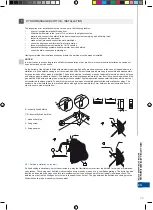
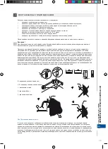
The system creates a large amount of small air bubbles in water. The air is supplied by nozzles installed on the bottom of
the bathtub. The example of this system setting is shown in picture 9.
DESCRIPTION:
10 air nozzles with peripheral inlet installed on the bottom of the bathtub,
air pump.
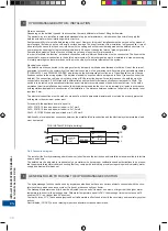
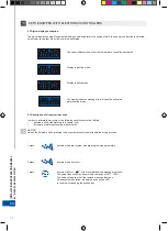
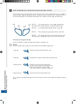
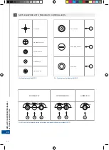
The air system is activated/deactivated by means of the C pushbutton (located on the upper bathtub surface) shown in
picture 5.
WATER SET – HYDROMatic
This system provides intensive and efficient body massage. The water jet also supplies air to the nozzle, thanks to which
a large amount of air bubbles are created at the nozzle mouth. The result of the massage depends on the amount of air
supplied and the pump power. An example of this system setting is shown in picture 10.
DESCRIPTION:
6 lateral directional nozzles installed on the bathtub’s side surfaces,
2 whirlpool nozzles for foot massage,
4 mini-nozzles for back massage,
water pump.
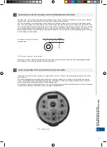
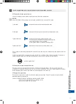
The water massage is activated/deactivated by means of the A pushbutton located on the upper bathtub surface. The
Water system is also supplied with air in order to make the massage more intensive. Knob B (picture 7) is used for nozzle
aeration.
The system is not able to operate properly unless the bathtub is filled up with water to the required level.
WATER-AIR SYSTEM – DUOMatic
This system combines the water and air systems, which gives the relaxing and refreshing action of both systems to enhance
the user’s comfort. An example of this system setting is shown in picture 11.
DESCRIPTION:
Water massage:
6 lateral directional nozzles installed on the bathtub’s side surfaces,
2 whirlpool nozzles for foot massage,
4 mini-nozzles for back massage,
water pump
Air massage:
10 air nozzles with peripheral inlet installed on the bottom of the bathtub,
air pump
The water-air massage function is activated/deactivated by means of A, B and C elements (located on the upper bathtub
surface) shown in picture 7.
The system is not able to operate properly unless the bathtub is filled up with water to the required level.
•
•
•
•
•
•
•
•
•
•
•
•
7
SETS EQUIPPED WITH PNEUMATIC CONTROLLERS
Summary of Contents for AirMATIC
Page 2: ...www cersanit com...
Page 47: ...47 INSTALLATION AND OPERATION MANUAL BATHTUB WITH MASSAGE SYSTEM EN...
Page 48: ...48 RU 1 Cersanit T 2 Ma a 3 MO T M...
Page 49: ...49 RU 3 MO 3 4 10 15 2 5 B C D 1 2 3 1 a a b B b 1 2 3 C D 1 2 3...
Page 51: ...51 4 O temp 38o C 3 3 4 3 4 cm 5 4 RU...
Page 52: ...52 5 5 1 O MENU SET RU...
Page 54: ...54 RU 5 5 2 O c 5 3 O 1 2 1 40 100...
Page 55: ...55 RU 2 3 4 5 5 4 O 1 2 1 40 100 5...
Page 56: ...56 RU 5 2 wci ni cie 3 wci ni cie 4 wci ni cie 5 wci ni cie 5 5 O 5 6 5 6 1 A 3 5...
Page 57: ...57 RU 5 6 2 O 45 1 100 2 5 6 3 1 2 5 10 a Er2 Er1...
Page 58: ...58 RU 5 6 4 1 2 3 5 6 5 5 6 6 Ko 5 Ko O Er1 Er2 Er3 Er4...
Page 59: ...59 RU 6 MICRO 5 6 1 O LED 1 M LED2 2 od MIN MAX MAX LED3...
Page 61: ...61 RU MICRO 6 3 O 1 2 1 LED4 2 20 6 4 O 6 5 O 45 6...
Page 62: ...62 RU 1 100 LED1 2 6 6 1 2 20 MICRO 6...
Page 63: ...63 RU AIRMatic 9 O 10 C 5 HYDROMatic 10 O 6 2 4 A B 7 DUOMatic 11 O 6 2 4 10 A B C 7 7...
Page 64: ...64 RU 7 EURO 6 MATIC A B C 7 MATIC DUOMATIC HYDROMATIC AIRMATIC A B C C B A C 8 O MATIC...
Page 65: ...65 RU 9 AIRMatic 7 10 HYDROMatic 11 DUOMatic...
Page 66: ...66 RU a 10 10 5 8 9 O O 800 1200 2000...
Page 67: ...67 RU...
Page 87: ...87 RO INSTRUC IUNI DE MONTAJ I NTRE INERE A C ZILOR DE BAIE CU SISTEME DE MASAJ...
Page 107: ...107...

