34
5.
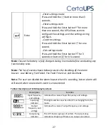
Confirm settings: Press and hold the Enter
button
for one second, and the UPS will then return to settings mode.
6.
Exit Settings mode: Press and hold the Enter button
for 3 seconds or
button
for 0.5 second to exit settings mode.
5. Communication Port
5.1 RS-232 and USB communication ports
To establish communication between the UPS and a computer connect your
computer to one of the UPS communication ports using an appropriate
communication cable (USB or RS-232 lead). When the communication cable is
installed power management software (Winpower) can exchange data between
the computer and the UPS. The software polls the UPS for detailed information
on the status of the power environment. The software can be configured so that
in the event of a power cut it initiates the saving of all data and the safe
shutdown of the protected equipment. The pin configuration for the RS-232
communication port is identified below and the pin functions are described in
Table 5.
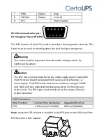
Table5. DB9 Female (RS-232 + dry contact)
PIN # Description
I/O
Function Explanation
1
BATLOW
Output
Battery low
2
RXD
Input
RXD
3
TXD
Output
TXD
4
DTR
Input
N/A
5
Common
--
Common (tied to chassis)
6
DTR
Input
N/A


