background image


-30- 

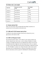
10.4 Dimensions and weights 

Model No. 

Dimensions W×H×
(mm) 

Net Weight 
(kg) 

C400-010-B


144*228*356 

9.2kg 

C400-010-C


102*228*346 

3.9kg 

C400-020-B


190*327*399 

17.4kg 

C400-020-C


102*327*390 

6.4kg 

C400-030-B


190*327*399 

22.7kg 

C400-030-C


102*327*390 

6.4kg 


11. Communication Port 

On the rear panel of the UPS (see Appendix), USB & RS232 connectors are 

standard, as is a Slot for optional connectivity cards. 


11.1 USB and RS-232 Communication Ports   

To establish communication between the UPS and a computer by use an 
appropriate communication cable. 
 

11.2 USB for HID power device   

The USB interface offers feature “smart battery” which supports HID (Human 

Interface Device) Power Device Class, no more software installation is needed. 

Computer’s OS (Operating System) such as Windows/Linux/Mac OS comes with 

an embedded power management and monitoring function. When a computer 

connects to UPS via USB cable, the UPS will be automatically recognised by the OS 

as a “HID UPS Battery”, and user can configure the alarm action in the event of 

low battery, such as shutting down the computer automatically. UPS with this 

feature is also ideal as a back-up power for NAS (Network-Attached Storage). 

Summary of Contents for C400-010-B

Page 1: ...C400 1000 3000 VA Tower 1000 3000VA Installation Manual Service and support WWW CERTAUPS COM INFO CERTAUPS COM T 44 0 1246 431 431 ...

Page 2: ...ION 10 5 1 INSPECTION 10 5 2 CONNECTION 10 5 3 BATTERY RECHARGE 14 5 4 TURN ON THE UPS 14 5 5 TEST FUNCTION 14 5 6 TURN OFF THE UPS 15 5 7 AUDIBLE ALARM MUTE FUNCTION 15 6 OPERATING MODE FOR ALL MODELS 16 6 1 LINE MODE 17 6 2 BATTERY MODE 18 6 3 BYPASS MODE 18 6 4 NO OUTPUT MODE 19 6 5 EPO EMERGENCY POWER OFF 19 6 6 ECO MODE ECONOMY MODE 20 6 7 CVCF MODE 20 6 8 ABNORMAL MODE 20 7 SETTING BY LCD MO...

Page 3: ...ES AT 25 C IN MINUTES 29 10 4 DIMENSIONS AND WEIGHTS 30 11 COMMUNICATION PORT 30 11 1 USB AND RS 232 OPTIONAL COMMUNICATION PORTS 30 11 2 USB FOR HID POWER DEVICE 30 11 2 AS400 INTERFACE OPTIONAL 31 11 1 CMC INTERFACE OPTIONAL 31 11 2 NMC INTERFACE OPTIONAL 31 12 SOFTWARE 32 APPENDIX REAR PANEL IEC 33 ...

Page 4: ... Do not install the UPS near water or in damp environment Do not install the UPS where it would be exposed to direct sunlight or near other heat sources Do not connect appliances or items of equipment which would overload the UPS e g laser printers etc to the UPS output Place cables in such a way that no one can step on or trip over them Use a reliable earth source Only connect the UPS to an earth...

Page 5: ...ation Do not disconnect the mains cable on the UPS or the building wiring socket grounded shockproof socket during operation as this would remove the ground to the UPS and of all connected loads The UPS features its own internal current source batteries There is risk of electrical shock from the UPS output sockets or output terminal block even if the UPS is not connected to mains supply In order t...

Page 6: ... voltage is present before servicing Batteries have a high short circuit current and pose a risk of shock Take all precautionary measures specified below and any other measures necessary when working with batteries remove all jewelry wristwatches rings and other metal objects only use only tools with insulated grips and handles When changing batteries always replace with the same quantity and the ...

Page 7: ...C2 Harmonic current IEC EN 61000 3 2 Voltage fluctuation and flicker IEC EN 61000 3 3 EMS ESD IEC EN 61000 4 2 Level 3 RS IEC EN 61000 4 3 Level 3 EFT IEC EN 61000 4 4 Level 4 SURGE IEC EN 61000 4 5 Level 4 CS IEC EN 61000 4 6 Level 3 MS IEC EN 61000 4 8 Level 4 Voltage Dips IEC EN 61000 4 11 Low Frequency Signals IEC EN 61000 2 2 ...

Page 8: ...wer disturbances A rectifier converts the alternating current from the socket outlet to direct current This direct current charges the batteries and powers the inverter On the basis of this DC voltage the inverter generates a sinusoidal AC voltage which permanently supplies the loads Computers and periphery are thus powered entirely by the mains voltage In the event of power failure the maintenanc...

Page 9: ...el Single Phase input Single Phase Output 3 C400 020 B 2000VA 1800W Tower Standard model Single Phase input Single Phase Output 4 C400 020 C 2000VA 1800W Tower Long Backup time model Single Phase input Single Phase Output 5 C400 030 B 3000VA 2700W Tower Standard model Single Phase input Single Phase Output 6 C400 030 C 3000VA 2700W Tower Long Backup time model Single Phase input Single Phase Outpu...

Page 10: ...m battery test By pressing this Button the UPS can do a battery test within Line mode ECO mode or CVCF mode OFF Button When mains power is normal the UPS system switches to No output or Bypass mode by pressing OFF Button and the inverter is off At this moment if Bypass is enabled then the output sockets are supplied with voltage via the bypass if the mains power is available Deactivate acoustic al...

Page 11: ...utton 4 2 LCD description Figure 4 2 LCD display LCD icon function Display Function Input Information Indicates input voltage frequency value which are displayed alternately Indicates the input is connected with mains and the input power is single phase input Output Information Indicates output voltage frequency value which are displayed alternately ...

Page 12: ...n Indicates the battery capacity Every grid represents the capacity of 20 Mode Fault Warning Information Indicates the operating mode Fault type Warning type or battery remaining time several warning types at the same time could be displayed alternately Misc Indicates the UPS is in setting mode Indicates the UPS is in Fault mode or has some warnings ...

Page 13: ... power cord please use the corect socket with protection against electric current and pay attention to the capacity of the socket The UPS System has an input breaker on the standard cabinet 2 UPS Output Connection The output sockets and types of the UPS are shown below Model No Output Socket IEC pcs C400 010 B 4 C13 C400 010 C 3 C13 C400 020 B 4 C13 C400 020 C 6 C13 C400 030 B 4 C13 1 C19 C400 030...

Page 14: ...nal block according to Figure 5 1 and the table 5 1 Figure 5 1 Output Connection diagram of C400 030 C IEC model Table 5 1 Terminal position Wire function Terminal wire size rating Tightening torque L Line Out 1 5mm2 2 5mm2 14AWG 12AWG 0 5Nm 4 4 Lb In N Neutral Out Output Ground ...

Page 15: ...nnection procedure is very important Any incompliance may result in the risk of electric shock Therefore the following steps must be strictly complied with Prepare the battery cable with Standard type connector which should be able to carry the current If there is a battery breaker then turn it off first Then connect the battery cable to the Standard type battery connector on the real panel Connec...

Page 16: ...ll be active and the UPS will stop output power immediately Normally open Normally the EPO connector is open on the rear panel Once the connector is closed with a wire the UPS will stop output until EPO status is reset Disable EPO status Enable EPO status Normally closed Normally EPO connector is closed with a wire on the rear panel Once the connector is open the UPS will stop output until the EPO...

Page 17: ...mains power is not connected to the UPS the UPS still can be turned on by just simply pressing on button continuously for more than 1 second with external batteries connected the UPS will get into the Battery mode and the LCD screen will indicate the state of the UPS Note The default setting for bypass mode is no output after UPS is connected to mains power and the breaker is turned on This can be...

Page 18: ... in battery mode the audio alarm is able to be muted by pressing the ON button continuously for more than 1 second Moreover the audible alarm will be active again when the battery reaches low status to remind the end user that UPS output power will shutdown soon If the audible alarm is not required in bypass mode the audible alarm is able to be muted by pressing the OFF button continuously for mor...

Page 19: ...perating mode string and the warning string will be shown circularly Once a fault comes forth all previous warnings will not be shown again only the fault string will be presented Table 6 1 Operating Mode Operating mode Code No output mode STbY Bypass mode bYPA Line mode LINE Battery mode bATT Battery test mode TEST ECO mode ECO Converter mode CVCF NO Status Alarm 1 Battery mode Beep once every 4 ...

Page 20: ...t SHOR Overload fault OVLD Inverter soft start fail ISFT Bus soft start fail bSFT Over temperature fault OVTP Inverter Volt Low INVL Inverter Volt High INVH Bus volt over bUSH Bus volt Low bUSL Bus short bUSS Inverter NTC open NTCO Emergency Power Off EPO 6 1 Line mode The LCD display in Line mode is shown as figure 6 1 The information about the mains power the battery level the UPS output and the...

Page 21: ...s When the UPS is running in battery mode the buzzer beeps once every 4 seconds If the ON button on the front panel is pressed for more than 1 second the buzzer will stop beeping in silence mode Press the ON button once again for more than 1 second to resume the alarm function Figure 6 2 Battery mode 6 3 Bypass mode The LCD display in bypass mode is shown as figure 6 3 The information about the ma...

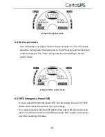
Page 22: ...he STbY string indicates UPS working in the No output mode Figure 6 4 No output mode 6 5 EPO Emergency Power Off It is also called RPO Remote Power Off On LCD display the word of EPO will be presented in the position of output voltage It is a special status which the UPS will shut the output off and send out an alarm The UPS cannot be turned off by pressing OFF button on the panel only after reset...

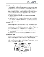
Page 23: ...lications involving sensitive loads 6 7 CVCF mode CVCF Constant Voltage Constant Frequency which is also called converter mode UPS will work in frequency free run with a fixed output frequency 50Hz or 60Hz Once the mains are lost or abnormal the UPS will transfer to battery mode and the load is supplied continuously by the battery 1 CVCF mode can be enabled through the LCD setting or the software ...

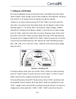
Page 24: ...wn if the Enter button is pressed again the string 220 stop flickering the output volt is changed to 220V if the Select button is pressed for more than 1 second the next flickering string 230 appear the order of flickering string is 220 230 240 220 230 Press Enter button to confirm the output voltage what you want Figure 7 1 Setting by LCD To exit the settings mode press once on the Enter button t...

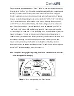
Page 25: ...Ah could be selected from 005 to 300 Here 005 means 5Ah total external battery Charger Current could be selected 3 0 6 0 for C400 010 C and 1 5 3 0 4 5 6 0 for C400 020 030 C Here 3 0 means 3A charger The battery remaining time function could be selected in 000 or 001 Here 000 means battery remaining time function is disabled then the battery remaining time will not display on the LCD in battery m...

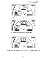
Page 26: ... 23 Step 4 MOdE after pressing the Select button UPS is flickering after pressing the Enter button Step 2 OPF after pressing the Select button Step 3 bYPA after pressing the Select button ...

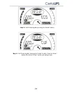
Page 27: ... 24 Step 5 ECO flickering after pressing the Select button Step 6 CVF flickering after pressing the Select button Press the Enter button Short touch Enter button exit setting mode ...

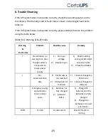
Page 28: ...n no warning tone even though system is connected to mains power supply 1 No input voltage 2 Breaker open 1 Check building wiring socket outlet and input cable 2 Check the Breaker No Communication data 1 RS232 wire is not matched 2 USB wire is not matched 1 check or change the RS232 wire 2 check or change the USB wire Emergency supply period shorter than nominal value 1 Batteries not fully charged...

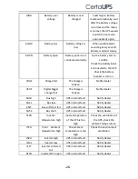
Page 29: ...dealer dCHF Digital bigger charger fail The charge is broken Notify dealer bUSH Bus high UPS internal fault Notify dealer bUSL Bus low UPS internal fault Notify dealer bSFT Bus soft start fail UPS internal fault Notify dealer bUSS Bus short UPS internal fault Notify dealer TEPH Inverter temperature high Inside temperature of the UPS is too high Check the ventilation of the UPS check the ambient te...

Page 30: ...r some loads are failed SITE Site fail Phase and neutral conductor at input of UPS system are reversed Rotate mains power socket by 180 or connect UPS system EPO EPO active EPO function is enabled Plug into the EPO switch Please have the following information at hand before contacting the After Sales Service Department 1 Model number serial number 2 Date on which the problem occurred 3 LCD display...

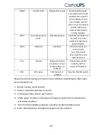
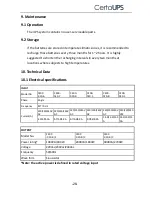
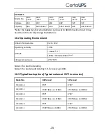
Page 31: ... Data 10 1 Electrical specifications INPUT Model No C400 010 B C400 020 C C400 030 B C400 010 C C400 020 B C400 030 C Phase Single Frequency 40 70 Hz Current A 220 230 240V AC 220 230 240V AC 220 230 240V AC 220 230 240V AC 220 230 240V AC 220 230 240 VAC 4 9 4 7 4 5A 5 7 5 4 5 2A 9 7 9 3 8 9A 9 7 9 3 8 9A 14 5 13 9 13 3 A 14 5 13 9 13 3A OUTPUT Model No C400 010 B C C400 020 B C C400 030 B C Powe...

Page 32: ...ronment Ambient Temperature 0oC to 40oC Operating humidity 95 Altitude 1000m Note 1 1000m Altitude 3000m Note 2 Storage temperature 25 C 55 C Note 1 the load no derating Note 2 the load should derating 1 for every up 100m 10 3 Typical backup time Typical values at 25 C in minutes Model No 100 Load 50 Load C400 010 B 5 00 8 30 C400 010 C 15 00 Base on 1EBM 25 30 Base on 1EBM C400 020 B 5 00 8 30 C4...

Page 33: ...nd a computer by use an appropriate communication cable 11 2 USB for HID power device The USB interface offers feature smart battery which supports HID Human Interface Device Power Device Class no more software installation is needed Computer s OS Operating System such as Windows Linux Mac OS comes with an embedded power management and monitoring function When a computer connects to UPS via USB ca...

Page 34: ...face Optional It provides connection to Modbus protocol with standard RS485 signal To see more detail please check the CMC user manual 11 2 NMC Interface Optional NMC Network Management Card allows the UPS to communicate in a variety of networking environments and with different types of devices NMC achieves a remote management for the UPS through internet intranet Please contact your local dealer...

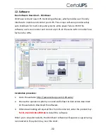
Page 35: ...control any UPS on the same LAN no matter how far from the UPSs Installation procedure 1 Go to the website http www certaups com software 2 Choose the operation system you need and follow the instruction described on the website to download the software 3 When downloading all required files from the internet enter the product key 511C1 01220 0100 478DF2A to install the software When your computer ...

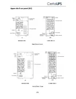
Page 36: ... 33 Appendix Rear panel IEC Back Rear View Back Rear View C400 010 B C400 010 C C400 020 C C400 020 B ...

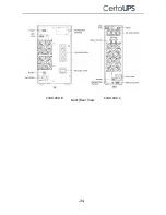
Page 37: ... 34 Back Rear View C400 030 B C400 030 C ...

Reviews: