background image


C400R User Manual 

Page 18 


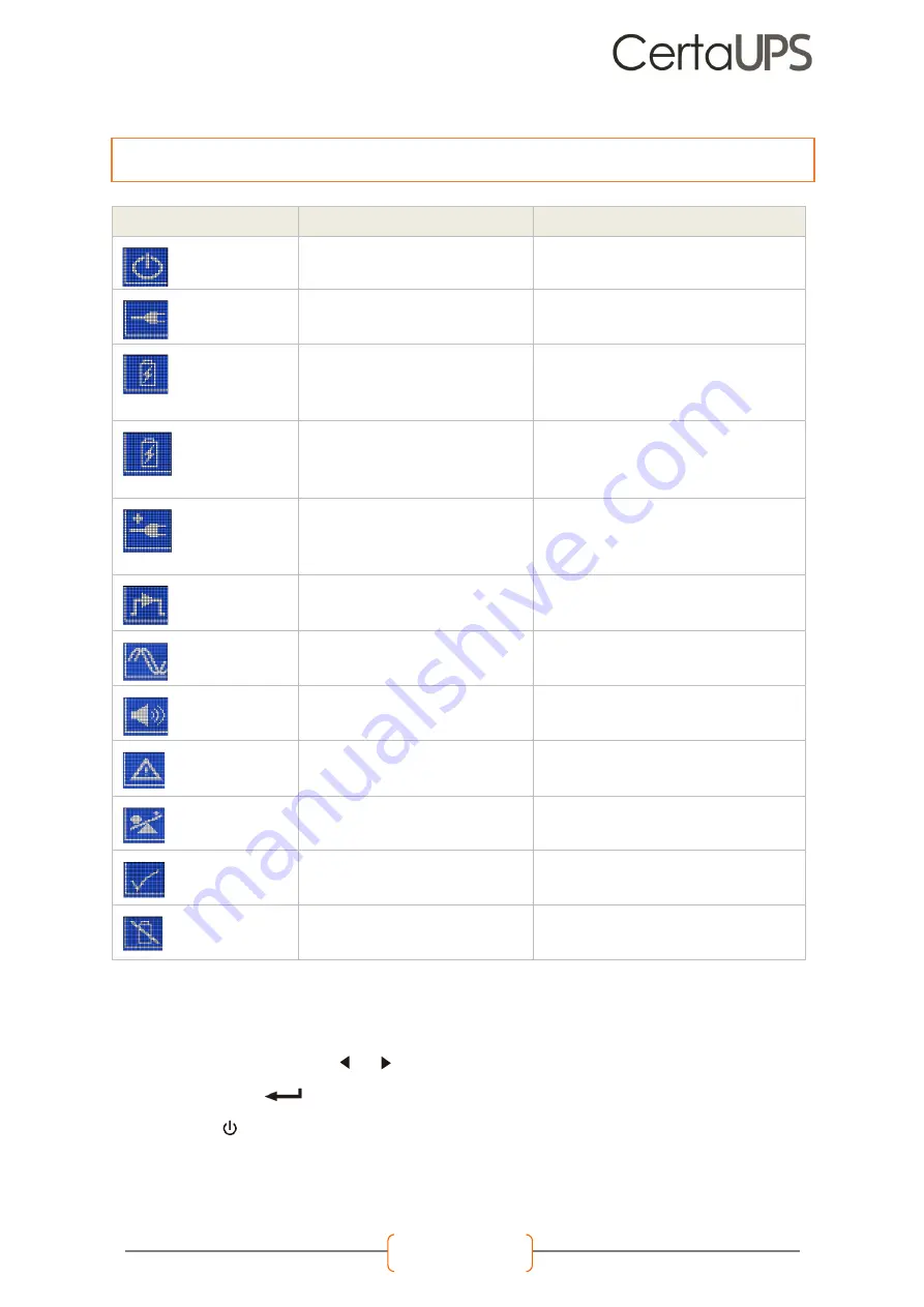
OPERATION STATUS 

CAUSE 

DESCRIPTION 

Standby mode 


The UPS is Off 

UPS is in stand by mode without any output 

Online mode 


The UPS is operating normally 

The UPS is powered and protecting the equipment 

Battery mode 


(1 beep every 4 seconds) 

Mains failure has occurred, the UPS is in Battery 

mode 

The UPS is powering the equipment from battery power. 

Prepare equipment for imminent shutdown 

End of backup time 


(1 beep every 1 second) 

The UPS is in Battery mode and the battery is 

nearing depletion 

This warning is approximate, and the actual time to 

shutdown may vary depending on the configuration and 

load. 


High-Efficiency mode 


(10ms transfer time in HE) 

The UPS is operating in High-Efficiency mode 

Once mains power is lost or out of tolerance, the UPS will 

transfer to Line/Battery mode and the load is supplied 

from battery power. 

Bypass mode 


An overload/fault has occurred, or the UPS has 

been instructed to enter Bypass mode. 

Equipment is powered but not protected by the UPS. 

Converter mode 


The UPS is operating in converter mode, where 

the UPS will provide fixed output frequency (50Hz 

or 60Hz) 

In converter mode, Once the mains power is lost or out of 

tolerance. The UPS will transfer to battery mode and the 

load is supplied continuously 

Warning 


Warnings are present, this will not necessarily 

affect operation. 

The UPS continues working, but the problem should be 

identified and resolved immediately, or it could prevent 

normal operation of the UPS 

Fault 


A fault has been detected 

The UPS will immediately cut off the output/transfer to 

bypass and present an alarm 

Overload 


The load exceeds the capacity of the UPS 

The excess load should be removed to meet the UPS 

output rating 

Battery test 


UPS is executing a battery test 

The UPS is performing a Battery test. This is a normal 

scheduled self-maintenance test and is part of normal 

operation 

Battery fail 


The UPS has detected a fault or a battery is 

disconnected 

The battery failure symbol is shown and UPS will alarm. The 

fault should be investigated by a qualified UPS engineer 


DISPLAY FUNCTIONS 


The UPS is controlled using basic button functions via the LCD panel, basic operation functions include: 


Use the two middle buttons (    and    ) to scroll through the menu structure.  


Press the Enter ( 

 ) button to select an option.  


Press the    button to cancel or return to the UPS status summary screen. 


When starting the UPS, the display is in the default UPS status summary screen. 


IF ANY OTHER STATUS APPEARS, OR FOR FURTHER GUIDANCE ON WHAT TO DO PLEASE SEE THE TROUBLESHOOTING 

SECTION ON PAGE 28 OR CONTACT A CertaUPS REPRESENTIVE 


Summary of Contents for C400R Series

Page 1: ...ON AND USER GUIDE THE C400R SERIES An uninterruptible power supply UPS incorporating online double conversion technology which eliminates all mains power disturbances www certaups com For assistance please contact your local CertaUPS partner ...

Page 2: ...1 C400R RACKMOUNT MODEL INSTALLATION 13 WIRING Error Bookmark not defined C400R SERIES STARTUP AND SHUTDOWN 15 STARTING THE UPS WITH MAIN POWER PRESENT 15 STARTING THE UPS FROM BATTERY 15 UPS SHUTDOWN WITH MAINS POWER 16 UPS SHUTDOWN WITHOUT MAINS POWER 16 C400R SERIES OPERATION 17 LCD DESCRIPTION 17 DISPLAY FUNCTIONS 18 USER SETTINGS 19 LCD MENU SYSTEM 20 MAIN MENU 20 UPS STATUS 20 MEASUREMENTS M...

Page 3: ...TERFACE CARDS OPTIONAL 5 SOFTWARE 5 UPS MAINTENACE 6 UPS CARE 6 TRANSPORTING THE UPS 6 STORING THE UPS 6 BATTERY REPLACEMENT 7 REPLACING THE EBM 7 RECYCLING A UPS 8 TECHNICAL DATA 10 ELECTRICAL SPECIFICATION 11 OPERATING ENVIROMENT 11 RUNTIMES 12 DIMENSIONS AND WEIGHTS 12 ...

Page 4: ...person 55 kg 120 lb Forklift Before any handling please ensure that the following precautions are taken QUALIFIED PERSONNEL Any persons servicing the UPS must be qualified and knowledgeable in UPS technology and batteries CLOTHING Correct PPE should always be worn POWER OFF Ensure all mains power is disconnected before starting work TOOLS always use insulated tools Do not lay tools down near the U...

Page 5: ...within this manual DO check that the indicators on the rating plate correspond to the AC powered system and to the actual electrical consumption of all the equipment to be connected to the UPS DO ensure the outlet is installed near the UPS and is easily accessible DO store the UPS in a dry environment DO keep the UPS in a well ventilated area Additional considerations To reduce the risk of fire or...

Page 6: ... Phase output 6 C400R 030 C 3000VA 2700W Rack Charger model Single Phase input Single Phase output THE TECHNOLOGY The C400R UPS series uses online double conversion technology which ensures that clean and stable power is always provided An online UPS operating in line mode always provides a consistent supply of AC power to the load This is done by using the battery and the inverter to ensure a cle...

Page 7: ...l monitoring probe SNMP required C MOD1 Modbus interface MBSRACK 1 3 Rack mountable Maintenance bypass switch UPS STANDARDS DESCRIPTION STANDARD Conduction Radiation IEC EN 62040 2 Harmonic Current IEC EN 61000 3 2 Voltage Fluctuation IEC EN 61000 3 3 ESD IEC EN 61000 4 2 RS IEC EN 61000 4 3 EFT IEC EN 61000 4 4 Surge IEC EN 61000 4 5 CS IEC EN 61000 4 6 MS IEC EN 61000 4 8 Voltage Dips IEC EN 610...

Page 8: ... condensation The UPS EBM is heavy Follow any special precautions provided on the carton Unpack the equipment and remove shipping carton and all the packaging materials DO NOT lift the using the front panel and rear panel Rackmount Tower model C400R BOX CONTENTS CHECKLIST C400R Series UPS Rack rails USB A to B Software CD Quick Start Guide Warranty Card Horizontal stabilising bracket PLEASE ENSURE...

Page 9: ...perature before turning on The UPS needs to be fully charged to achieve full autonomy C400R TOWER MODEL INSTALLATION Tools required Insulated screwdriver Box Contents STEP ONE Ensure utility power is switched off STEP TWO Carefully place the UPS within the stands STEP THREE Pull out the LCD panel and carefully rotate it taking care not to damage the cable STEP FOUR If not installing additional EBM...

Page 10: ...x To connect multiple EBMs in tower form for use the same method as assembling the UPS EBMs in rack form To install multiple EBMs connect an Earth line between the UPS and the first EBM and then connect a second Earth line between the first EBM and the second EBM Take off the front panel as instructed in the previous steps This then enables you to connect the battery terminal A from the UPS to the...

Page 11: ...ll the unit to the rack cabinet in a suitable U space Pre install rail kit Slide the UPS into the rack rails and lock it into the rack enclosure Tighten the screws The UPS is now ready for cabling unless you are installing EBMs STEP FOUR If not installing additional EMBs skip straight to step six Using the same method as assembling the UPS in rack form Connect the earth line between mounting point...

Page 12: ...connect a second Earth line between the first EBM and the second EBM Take off the front panel as instructed in the previous steps This then enables you to connect the battery terminal A from the UPS to the EBM terminal B shown below Then connect the battery terminal D from the first EBM to the battery terminal E of the second EBM The user then needs to reassemble the front panel STEP SIX Plug the ...

Page 13: ...ormal the UPS will transfer to battery mode without output interruption to the UPS 5 When the UPS is online the icon will be displayed STARTING THE UPS FROM BATTERY Before using this feature the UPS must have been powered by utility power with output enabled at least once to ensure the unit is adequately charged After connecting the UPS to any EBMs you should wait for at least 10s before pressing ...

Page 14: ... bypass mode immediately 3 In order to cut off the UPS output remove the mains power supply A few seconds later the LCD display will shut down and no output power is available from the UPS output terminal UPS SHUTDOWN WITHOUT MAINS POWER To shutdown the UPS without mains power 1 Power off the UPS by pressing the button continuously for more than 3 seconds and the UPS output will stop 2 A few secon...

Page 15: ...mary screen press this button for 1s to enter the main menu tree Exit main menu Press this button for 1s to exit the present menu to default system status display menu without executing a command or changing a setting Scroll up Press this button 1s to scroll up the menu option Scroll down Press this button for 1s to scroll down the menu option Enter next menu tree Press this button for 1s to selec...

Page 16: ...l transfer to battery mode and the load is supplied continuously Warning Warnings are present this will not necessarily affect operation The UPS continues working but the problem should be identified and resolved immediately or it could prevent normal operation of the UPS Fault A fault has been detected The UPS will immediately cut off the output transfer to bypass and present an alarm Overload Th...

Page 17: ...Password Key the password USER Language English Chinese English User password Disabled Enabled Disabled Audible alarm Enabled Disabled Enabled Output voltage 220V 230V 240V Can be changed in Standby mode and bypass mode 230V Output frequency Autosensing 50Hz 60Hz Autosensing Power strategy Normal High efficiency Converter Normal Auto bypass Enabled Disabled Enabled Auto restart Enabled Disabled Au...

Page 18: ...screen Press for more than 1 second and the display will enter the main menu The main menu includes six areas UPS status Event log Measurement Control Identification Settings The following section outlines the working schematic for each of the above menu items UPS STATUS From the main menu pressing on the UPS status option the display will enter the UPS status menu By pressing for 1 second at any ...

Page 19: ...ion is available within this menu including output voltage and frequency output current load capacity input voltage and frequency etc By pressing or the displayed measurement can be changed Pressing for 1 second at any time will return the display to the last main menu Pressing at any time will return the display to the UPS summary screen ...

Page 20: ...UPS to carry out a battery self test Reset fault status when a fault occurs the UPS will stay in fault mode and alarm until acknowledged To clear the alarm enter the Reset Fault status menu to clear the error The UPS will stop alarming and return to bypass mode The cause of the fault should be established and cleared prior to the ups being returned to normal operation Restore factory settings all ...

Page 21: ...ease contact your local CertaUPS partner for further information before configuring the UPS Most settings in this menu require the UPS to be in bypass to take effect MISCONFIGURATION COULD RESULT IN FAILURE OF THE EQUIPMENT AND PERSONAL INJURY ...

Page 22: ...onnection allows the UPS to be powered off by changing the state of either a normally open or normally closed circuit The default state of the connection can be configured via the LCD display settings Normally open Normally the EPO circuit is open on the rear panel Once the connector is closed with a wire the UPS will stop output until EPO status is reset Normally closed Normally EPO connector is ...

Page 23: ... SMS Windows system log Scheduled UPS test Password security protection Remote monitor control via LAN Safety to shutdown multi system Selectable User Interface Background UPS parameter setting SNMP Central monitoring up to 1000 units Record logs for analysis Multi language support English Italian Turkish Spanish French Portuguese Polish Thai Germanic Russian and Japanese Requires a GSM modem not ...

Page 24: ...ns power Place the UPS on a flat stable surface with the front of the cabinet facing you Remove the UPS front cover Disconnect the internal battery connectors Replace the UPS front cover To avoid damage and to prevent DOA s always use a reputable courier for all equipment transportation STORING THE UPS Where UPS equipment is stored for a long period of time the batteries must be recharged every si...

Page 25: ... electrical shock or burn from high short circuit current Observe the following precautions Remove watches rings or other metal objects Use tools with insulated handles Do not lay tools or metal parts on top of batteries Wear rubber gloves and boots REPLACING THE EBM For the C400R rotation module If a PDU is connected to the UPS turn the MBS to bypass and switch off the input it is then safe to re...

Page 26: ... of waste electrical or electronic equipment WEEE in the trash For proper disposal contact your local recycling centre TROUBLESHOOTING The C400R series is designed for durable automatic operation It also provides alerts whenever potential operating problems occur Events are silent status information that are recorded into the Event log Example AC freq in range Alarms are recorded into the Event lo...

Page 27: ...re is too high Check environment and ventilation 11 BATTERY OPEN Batteries not connected correctly Check the EBM is correctly connected confirm the Battery breaker is on 13 SERVICE FAILURE Battery condition is preventing proper operation Consult you CertaUPS representative 41 42 43 UPS OVERLOADED The UPS is overloaded Remove noncritical load check for attached device failure 71 EPO ENABLED The EPO...

Page 28: ...T Internal UPS fault Consult you CertaUPS representative Check the alarm condition and perform the applicable action to resolve the condition If an alarm status changes the alarm will need to be silenced again TECHNICAL DATA BLOCK DIAGRAM ...

Page 29: ...quency 50 60Hz Waveform Sinusoidal BATTERIES Model No C400R 010 B C400R 010 C EBM C400R 020 B C400R 020 C EBM C400RR 030 B C400RR 030 C EBM Voltage 36V 36V 48V 48V 72V 72V Capacity 7Ah x 3 7Ah x 6 EBM 9Ah x 4 9Ah x 8 EBM 9Ah x 6 9Ah x 12 EBM OPERATING ENVIRONMENT Ambient Temperature 0 Cto 40 C Full load no de rating 40 C to50 C output power derated to 50 load Charger current derated 50 Operating h...

Page 30: ...s 81 Mins 176 Mins C400R 020 C C400R BB2 3 50 Min 73 Mins 116 Mins 261 Mins C400R 020 C C400R BB2 4 68 Min 102 Mins 159 Mins 334 Mins C400R 030 B NA 0 3 Mins 6 Mins 10 Mins 23 Mins C400R 030 C NA 0 0 Mins 0 Mins 0 Mins 0 Mins C400R 030 C C400R BB3 1 15 Mins 25 Mins 44 Mins 106 9 Mins C400R 030 C C400R BB3 2 31 Mins 50 Mins 87 Mins 186 Mins C400R 030 C C400R BB3 3 52 Mins 79 Mins 122 Mins 276 Mins ...

Page 31: ... User Manual Page 13 A FULL GLOSSARY OF TERMS CAN BE FOUND AT WWW CERTAUPS COM SUPPORT UPS GLOSSARY FOR FURTHER INFORMATION OR ASSISTANCE PLEASE CONTACT YOUR CertaUPS REPRESENTATIVE OR VISIT WWW CERTAUPS COM ...

Reviews: