background image

7

Fig. 8 

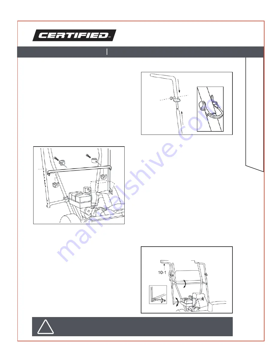
5. Assemble the legs of the frame 
supports together. Align the holes and 
slide the frame pin (#18) through. Fasten 
to lock in place.

6. Install the upper horizontal mounting bar.

a. Swivel the shorter legs of the frame
     support upwards until they are parallel to
     the ground.
b. Position the upper horizontal mounting bar
     as far as possible from the lower bar. Align
     the holes of the bar with any of the holes
     in the frame support.
c. Use 2 3/4" (#12) or 3 1/4"(#13)
     bolts and 1/4" locknuts (#14) to attach
     the bar to the handlebars.

7. Attach the frame supports to the upper 
horizontal mounting bar using hex bolts 
(#10) and 1/4" lock nuts (#14)

8. Check and adjust the frame supports. 
The shorter legs (Fig.10-1) of the frame 
supports should be parallel to the ground 
and spaced 28 1/2" apart.
If they are not parallel:

a. Put an adjustable wrench on the partially 
    flattened end of the lower bar.
b. Use the wrench as a level to rotate the bar.
c. Adjust until the legs are parallel

.

28 1/2" 

model number 060-3938-8

ASSEMBL

Y AND INS

TALLA

TION

contact us 1-855-867-5633

Fig. 9

Fig. 10

28 1/2" 

!

IMPORTANT! 

The upper bar may have to be rotated with the lower bar in certain setups.

Summary of Contents for 060-3938-8

Page 1: ...model number 060 3938 8 Please read and understand all instructions before use Retain this manual for future reference SNOWBLOWER CABIN IMPORTANT INSTRUCTION MANUAL ...

Page 2: ...s UB 5 Upper front rib marked as UF 6 Counterweight sandbag 7 Sandbag bracket 8 Cabin cover 9 Hex cap screw 1 4 20 x 1 10 Hex bolt 1 4 20 x 1 4 11 Bolt 1 4 20 x 1 3 4 12 Bolt 5 16 x 2 3 4 14 Locknut 1 4 20 15 Locknut 5 16 18 16 Hex cap screw 5 16 x 1 1 4 17 U clamp 3 4 18 Frame pin 1 1 4 x 1 4 diameter 19 U clamp 1 1 16 20 U clamp 1 1 18 21 U clamp 1 1 4 QTY 2 2 2 2 2 1 1 1 2 5 4 4 4 11 4 2 4 2 4 ...

Page 3: ...to prevent rust or damage Lock tools away and keep out of the reach of children PERSONAL PROTECTIVE EQUIPMENT 1 Always wear impact safety goggles that provide front and side protection for the eyes Eye protection equipment should comply with CSA Z94 3 07 or ANSI Z87 1 standards based on the type of work performed 2 Wear gloves that provide protection based on the work materials or to reduce the ef...

Page 4: ...ding areas thoroughly Operating the snowblower with the cabin restricts your field of vision 5 Watch for tree branches and other overhangs that might snag the cabin during operation 6 Install the counterweight to prevent the snowblower from tipping UNPACKING Remove the parts and accessories from the packaging and inspect for damage Make sure that all items in the parts list are included model numb...

Page 5: ...1 1 4 hex cap screws 16 into the bracket Fig 2 1 Do not fully tighten b Close the sandbag by folding the edge of the flap Fig 2 2 inwards and placing the fold Fig 2 3 in between the mounting brackets c Place the bag on top of the auger housing Do not cover any warning labels Position the bag so that the front edge of the augur housing meets the inside edge of the mounting bracket Tighten the cap s...

Page 6: ...ropriate U clamps 19 20 21 or 22 on the handle bars c Position the lower bar 17 to 24 above the ground to allow at least 6 1 2 of headroom inside the cabin d Use 2 3 4 12 or 3 1 4 13 bolts and 1 4 locknuts 14 to attach the bar to the handlebars Fig 5 Fig 6 Fig 7 The horizontal mounting bars 1 attach to the handlebars of the snowblower using a U clamp system that is designed to fit different machin...

Page 7: ... locknuts 14 to attach the bar to the handlebars 7 Attach the frame supports to the upper horizontal mounting bar using hex bolts 10 and 1 4 lock nuts 14 8 Check and adjust the frame supports The shorter legs Fig 10 1 of the frame supports should be parallel to the ground and spaced 28 1 2 apart If they are not parallel a Put an adjustable wrench on the partially flattened end of the lower bar b U...

Page 8: ...length of the straps as necessary 10 Install the lower ribs 3 9 Tighten all mounting bolts securely a Assemble the lower ribs together Secure using a 1 hex cap screw 9 and a 1 4 locknut 14 b Attach the lower ribs assembly to the frame supports using 1 3 4 bolts 11 and 1 4 locknuts 14 Use any of the holes in the frame support Ensure that the sides of the lower ribs that are marked LF are facing tow...

Page 9: ...the fabric areas with a clean moist cloth Do not use solvents STORAGE Store in a clean dry location Do not store while wet or damp to avoid mildew growth Avoid folding the windows when storing for long periods When not in use for an extended period tighten the connections before using the tool again DISPOSAL Recycle a tool damaged beyond repair at the appropriate facility Fig 20 CARE AND MAINTENAN...

Page 10: ...ts fluids tune ups or adjustments e this warranty will not apply where damage is caused by repairs made or attempted by others i e persons not authorized by the manufacturer f this warranty will not apply to any product that was sold to the original purchaser as a reconditioned or refurbished product unless otherwise specified in writing g this warranty will not apply to any product or part thereo...

Reviews: