background image

WARNING:  If the information in these instructions are not followed exactly, a fire or
explosion may result causing property damage, personal injury or death.

-

Do not store or use gasoline or other flammable vapours and liquids in the vicinity

of

this or any other appliance.

-

WHAT TO DO IF YOU SMELL GAS

Do not try to light any appliance.

Do not touch any electrical switch; do not use any phone in your building.

Immediately call your gas supplier from a neighbour's phone. Follow the gas
supplier's instructions.

-

Installation and service must be performed by a Corgi registered installer, service
agency or the gas supplier.

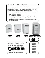
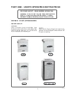
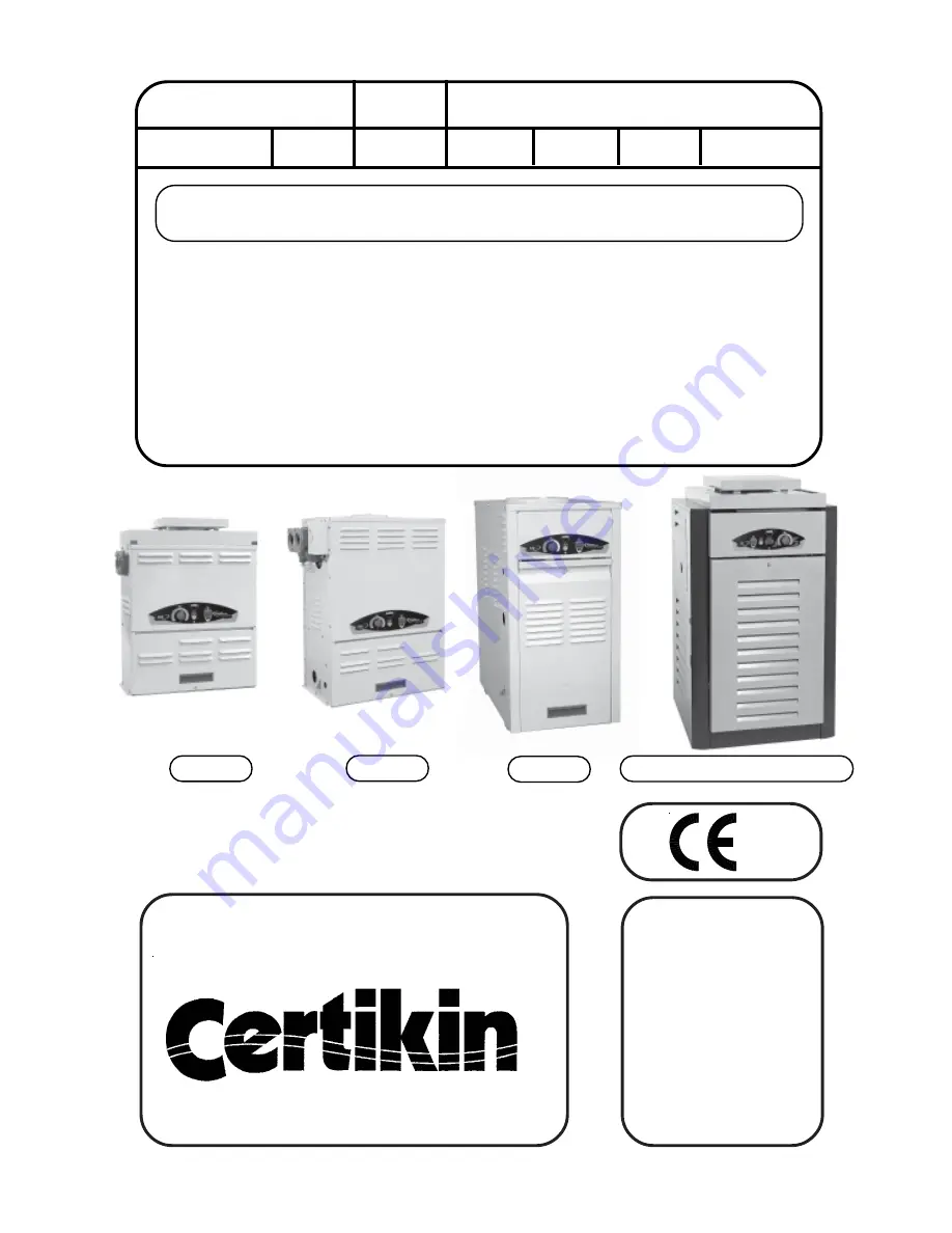
Operating, Installation and
Servicing Instructions for

Pool & Spa Heaters

M3556

Models:

MB055
MB105
MB155
MB185
MB265
MB405

0087

  MB055

              MB105

             MB155

   MB185 - MB265 - MB405

Natural Gas     L.P.G.

Serial No:

MODEL:

 MB055

MB105

MB155

MB185

MB265

MB405

Summary of Contents for MB055

Page 1: ...appliance Do not touch any electrical switch do not use any phone in your building Immediately call your gas supplier from a neighbour s phone Follow the gas supplier s instructions Installation and service must be performed by a Corgi registered installer service agency or the gas supplier Operating Installation and Servicing Instructions for Pool Spa Heaters M3556 Models MB055 MB105 MB155 MB185 ...

Page 2: ...ATIONS LPG GAS CATEGORY TYPE AND SUPPLY PRESSURE II2H3 G30 30 mbar G31 37 mbar MODEL 055 105 155 185 265 405 HEAT GROSS kW 14 65 12 9 26 67 38 98 49 53 71 5 108 4 INPUT Btu h 50 000 44 000 91 000 133 000 169 000 244 000 370 000 NET kW 13 2 11 9 24 54 35 86 45 57 65 8 99 8 Btu h 45 000 40 500 83 720 122 360 155 480 224 480 340 400 HEAT kW 11 0 10 06 20 8 30 4 38 63 55 8 84 58 OUTPUT Btu h 37 400 34...

Page 3: ...tions 16 Plumbing For Water Connections 16 Left Side Water Connection Conversion 20 Electrical Wiring 23 SECTION 3 SERVICING INSTRUCTIONS 23 General Location of Controls 25 Temperature Controls 25 Pressure Switch 26 High Limit 27 Pilot Safety 27 Burner Drawer Removal 27 Gas Valve Removal 27 Main Burner Orifice Removal 27 Pilot Removal Cleaning 28 Heat Exchanger Removal 28 Control Immersion Well Re...

Page 4: ...OSS OF LIFE 27 01 04 SECTION 1 START UP PROCEDURES BEFORE START UP BURNERS Clean air louvres of dust lint and debris Keep heater area clear and free from combustibles flam mable liquids and chemicals Do not obstruct the flow of combustion and ventilating air WATER Water must be flowing through the heater during operation Ensure that system is filled with water and the pump is operating 055 105 155...

Page 5: ...pliance and to replace any part of the control system and any gas control which has been under water OPERATING MODELS 055 105 and 155 Quick Start Check that the Electricity and Gas Supplies are on Turn on the Pool Pump Turn on the Heater with the switch on the Front Panel and set the desired temperature with the Pool Temperature Knob In a few seconds the Heater will fire Summary of Controls Left t...

Page 6: ...f On There is Pool Heating Demand and the Pool is not up to temperature Flashing The Pool Heating Demand is met the pool is up to temperature Pool Temperature Control Knob 16 C to 32 C or 41 C 60 F to 90 F or 106 F Maximum is changed in Setup Mode see Page 34 Rotate clockwise to increase the Pool Temperature The Setting Temperature is shown whilst rotating and for 3 seconds after To lock the requi...

Page 7: ...spa or hot tub use can cause drowsiness which could lead to unconsciousness and subsequently result in drowning 3 Pregnant Women Beware Soaking in water over 39 C 102 F can cause fetal damage during the first three months of pregnancy resulting in the birth of a brain damaged or deformed child Pregnant women should stick to the 38 C 100 F maximum rule 4 Before entering the spa or hot tub users sho...

Page 8: ...ight Chlorinators must feed downstream of the heater and have an anti siphoning device to prevent chemical back up into the heater when the pump is shut off NOTE High chemical concentrates from feeders and chlorinators that are out of adjustment will cause very rapid corrosion to the heat exchanger in the heaters Such damage is not covered under the warranty COLD WEATHER OPERATION MODERATE CLIMATE...

Page 9: ...at this manual be reviewed thoroughly before installing your pool spa heater If there are any questions that this manual does not answer please contact the supplier All heaters are inter changeable and can be used either indoor or outdoors The appropriate top designated for that type of use is required If desired the top can be changed at a later date to change from outdoor to indoor or vice versa...

Page 10: ...1989 CP341 Water Supply British Gas Publications IM2 Purging Procedures of Non domestic Gas Installations IM5 Soundness Testing Procedures for Industrial and Commercial Gas Installations 8 01 10 98 Sheet Metal 24 Gauge 0 7mm 12 Min 300mm 12 Min 300mm 4 Min 100mm Hollow concrete cinder block align holes and leave ends open Alternative method for providing a non combustible base Models 185 265 405 B...

Page 11: ...eater to inspect and delime the heat exchanger Heaters must not be installed under an overhang of less than 1 0m 3 feet from the top of the heater Three 3 sides must be open in the area under the overhang Roof water drainage must be diverted away from the heaters installed under overhangs with the use of gutters The point from where the flue products exit the heater must be a minimum of 1 25m 4 fe...

Page 12: ...lnotbelocatedinanarea where water sprinklers or other devices may cause water to spray through the cabinet louvres and into the heater This could cause heavy internal rusting or damage some electrical components and this would void the warranty It is recommended that the casing is cleaned and sprayed with WD40 or similar liquid and exposed threads on the manifolds are lightly coated in grease afte...

Page 13: ... the brackets and the top of the stack Place the stack over the inner adapter panel flanged hole and lower the louvered jacket top panel back into its original position Reinstall the four 4 No 10 flat head screws removed in step 1 above S8960 Draught Diverter Jacket Top Mounting Screws 8 Screw Hole Location 3 25 82 5mm Draught Diverter No 10 Screw 3 Flue Collector Part of Heater Inner Stack Adapte...

Page 14: ...70 2 3 5 105 127 5 1 NPT 48 105 3 5 8 155 152 6 2 NPT 62 135 3 5 8 825mm 32 1 2 Gas Connection 60mm 2 3 8 525mm 20 3 4 455mm 18 620mm 24 1 2 130mm 5 1 8 325mm 12 7 8 475mm 18 3 4 65mm 2 1 2 85mm 3 3 8 190mm 7 1 2 Gas Connection 65mm 2 1 2 325mm 12 3 4 510mm 20 690mm 27 1 4 1070mm 42 610mm 24 DIMENSIONS 105 Model Only DIMENSIONS 055 Model Only 835mm 32 7 8 ...

Page 15: ...570mm 61 SPECIFICATIONS DIMENSIONS 185 265 405 MODEL WIDTH FLUE DIA CONNECTIONS SHIPPING WEIGHT A B GAS WATER kg lbs mm in mm in APPLIANCE DIVERTER 185 464 18 1 4 150 6 2 NPT 86 8 191 5 5 12 265 568 22 3 8 175 7 2 PLASTIC 97 214 7 15 405 743 29 1 4 230 9 2 PLASTIC 115 253 9 20 DIMENSIONS 155 Model Only 610mm 24 1140mm 44 7 8 770mm 30 3 8 390mm 15 3 8 370mm 14 1 2 680mm 26 3 4 900mm 35 1 2 220mm 8 ...

Page 16: ...f the flue terminal above the draught diverter must ensure sufficient buoyancy to overcome the resistance of the bends and horizontal runs of the flue pipe The number of bends and length of horizontal run must be kept to a minimum to reduce resistance The chimney must terminate in a downdraught free zone The flue chimney design should avoid the formation of excessive quantities of condensate and f...

Page 17: ...ape on the gas line pipe thread A flexible sealant is recommended Models 055 and 105 are fittef with a BSP gascock all others have a gascock A minimum of 20 mbar 8 WG and a maximum of 22 mbar 8 W G upstream pressure under load and no load conditions are provided for natural gas or a minimum of 37mbar 14 W G and a maximum of 45 mbar 18 W G for propane gas GAS PRESSURE For LPG Heaters the gas pressu...

Page 18: ...m their pockets beware of the heatsink compound and disconnect the connections to the pressure switch and the overheat thermostat 3 Re route the sensors and cables to the other side 4 Remove the 12 bolts holding the Headers to their respective tubesheets 5 Clean the mating surfaces for the header gaskets and the gaskets themselves NB Use only silicone grease as a lubricant 6 Fit the headers on the...

Page 19: ...17 30 09 04 This page is intentionally left blank ...

Page 20: ...ea High tem perature 2 plastic pipe CPVC may be threaded directly into the Cast Iron header flanges This is not the same as the Schedule 80 PVC pipe which is also coloured grey PVC may be used immediately after the CPVC adapters NOTE If operating pressure above 2 bar 30psi are encountered then connection pipes must either be screwed into the flange or suitably anchored CAUTION NEVER install PVC di...

Page 21: ...hanging flow rates from the filter and changing pool temperatures This narrow range is needed to prevent damaging condensation on the burners which will occur if the heater runs for any length of time below 37 8 C It is also needed to inhibit scale formation in the tubes by maintaining temperatures well below accelerated scaling temperatures INTERNAL AUTOMATIC BY PASS VALVE Does not apply to 055 M...

Page 22: ...oved to BS1362 Connect the power supply as shown above Ensure that the cable is clamped in the cable clamp The wires must be such that the current carrying conduc tors become taut before the earth conductor in the event of the cable clamp not gripping the cable adequately NOTE Input power to the heater 220V should be supplied from the load Pump side of time clock or switch Connecting heater to con...

Page 23: ...een pauses Reset by turning supply off then on MAIN VALVE FAILED PILOT VALVE FAILED FLAME DETECTION FAILED FAILED TO LIGHT 1 13 14 and 15 16 17 and 18 5 7 and 10 30 09 04 PV GND PV MV MV PV TH 24 TR GND Y Y Y Led ABBEY ROBERTSHAW PILOT ROBERTSHAW FAULT INDICATIONS Reset by turning supply off then on OK WORKING FAILED TO LIGHT PILOT FAILED INTERNAL CHECK OFF or OFF ON FLASHING Bk Bk Bk Bk Bk Bk Bk ...

Page 24: ...flashes between pauses Reset by turning supply off then on MAIN VALVE FAILED PILOT VALVE FAILED FLAME DETECTION FAILED FAILED TO LIGHT 1 13 14 and 15 16 17 and 18 5 7 and 10 ROBERTSHAW FAULT INDICATIONS Reset by turning supply off then on OK WORKING FAILED TO LIGHT PILOT FAILED INTERNAL CHECK OFF or OFF ON FLASHING 30 09 04 GND PV MV MV PV TH 24 TR GND Y Led ROBERTSHAW ABBEY R Or Bk Y Y G Y 22 30 ...

Page 25: ...ners Pilot Gas Valve Solid State Thermostat Ignition Control Drain Valve Unitherm Governor Bronze Units Only Bypass Valve High Limits Overheat Thermostats High Limits Overheat Thermostats Unitherm Governor Drain Valve Solid State Thermostat Control Ignition Control Pressure Switch Gas Valve Thermal Fuse Pilot 23 01 10 98 105cont tif 8110 tif ...

Page 26: ...l 4 Rotate control panel down until panel stops Do not force NOTE Caution must be taken not to damage controls or wiring Jacket Top Panel Control Panel Mounting Screws 2 185 265 405 Models CONTROL PANEL REMOVAL 1 Remove 4 screws from sides of control panel 2 Rotate control panel down until panel stops Do not force NOTE Caution must be taken not to damage controls or wiring CONTROL PANEL MOUNTING S...

Page 27: ...seconds With a short press the Set temperature is displayed It will flash if the Lock is ON Pool Temperature Display This normally shows the Pool Temperature but also show the Setting Temperature when the Pool Temperature Control Knob is moved A Setting Dot is displayed whilst it is adjusted The Display is also used for commissioning and diagnostic purposes Page 34 Pool Demand LED Green Off There ...

Page 28: ...ETY SWITCH The heater is equipped with a thermal cutoff device to prevent flame roll out in the event that the heat exchanger becomes blocked This is a Single use typefusiblelinkorthermalfuse thatmustbereplaced when disabled by an over temperature condition caused by excessive restriction in the heat exchanger flue passage HIGH LIMITS The heater is equipped with one manual reset over heat thermost...

Page 29: ...wires that terminate at gas valve 7 Slide out burner tray 8 Reverse above procedure to re install NOTE IMPORTANT Reconnect Earth Connection 055 105 155 Models GAS VALVE REMOVAL 1 Remove burner tray See burner drawer removal procedure 2 Disconnect pilot tubing from gas valve 3 Remove gas valve with manifold from burner tray 4 Remove manifold from gas valve 5 Reverse above procedure to re install 18...

Page 30: ...isconnect wires at toggle switch 8 Remove capillary bulb from inlet outlet header 9 Disconnect press switch tube from return header 10 Disconnect hi limit wire from thermostat and pressure switch Remove overheat thermostat capilliary phial 11 Lift heat exchanger straight up from combustion chamber using caution not to damage refractory 12 Reverse above procedure to re install All Models CONTROL IM...

Page 31: ...nder outlet pipe connection 4 Remove spring and replace old U G with a new U G 5 Reverse above procedure to reinstall Extension Pieces 2 Auger with Carbide Tip Wire Brush To test the operation of the Unitherm Governor place in hot water over 43 C and watch for movement against spring If there is no movement replace unit 055 105 155 Models COMBUSTION CHAMBER REMOVAL 1 Remove heat exchanger See heat...

Page 32: ... Lowflow Scale forming in heat exchanger clean heat exchanger and check pool pH and total alkalinity Heater going on and off Dirty filter Backwash filter continuously Low water level in pool Raise water level External bypass setting out of adjustment Adjust bypass Pressure switch out of adjustment Adjust pressure switch Liming or scale forming on Pool water Recommended pH should be between heat ex...

Page 33: ...ate temperature in hr Heat rise hr Heater Output pool or spa Pool gallonage x 8 33 or refer to heater sizing chart This does not take into account heat loss due to weather Filter not running long enough Reset time clock Dirtyfilter Clean filter Gas line or meter undersized Refer to installation instructions Liming Bypassing too much water Inspect bypass for movement if no movement replace U G not ...

Page 34: ...BLE FOR SIGNS OF MELTING CHECK VALVE VALVE WIRING GAS SHUT OFF VALVES CHECK FLAME SENSE WIRE AND GROUND WIRE CHECK PILOT FLAME COVERS SENSE ROD CLEAN SENSE ROD CHECK VALVE VALVE WIRING CHECK LIMITS AND CIRCULATION FAN CHECK CONTINUITY OF SENSOR CABLE AND GROUND WIRE POOR GROUNDING MAY CAUSE OCCASIONAL SHUTDOWNS CHECK FOR EXCESSIVE HEAT AT FLAME SENSOR INSULATOR CHECK THERMOSTAT CHECK VALVE CHECK F...

Page 35: ... open circuit check combustion chamber for heat leaks Check 3 Amp fuse TEMPERATURE 40 C 40 5 C Control ok RESISTANCE ABOVE 15k OHMS OPEN CIRCUIT OR SHORT CIRCUIT Fix loose or broken wires Replace sensor if necessary MEASURED AND ESTIMATED RESISTANCE DON T MATCH Replace sensor Reconnect all leads and check out system Check voltage at 24 V terminals VOLTAGE BETWEEN 21 5 28 5 V Set control to max tem...

Page 36: ...isplays certain faults the display alternates between the two codes Display Reason Action 34 18 02 04 Power off then on If not corrected replace board Check connections if correct replace sensor Check connections if correct replace sensor Control board fault Pool sensor Open Circuit Pool sensor Short circuit Err No P oc P cc Logs The Control keeps a log of the number of times the Pressure Switch M...

Page 37: ...entigrade F or C 2 Maximum temperature 32 C 90 F 41 C 106 F PL or SPA 3 Filter Pressure Log Number of Operations Resets to zero Yellow Filter LED ON 4 Overheat Log Number of Operations Resets to zero Red Overheat LED ON 5 Hi Limit Log Number of Operations Resets to zero Red PCB LED ON 6 Thermal Fuse Log Number of Operations Resets to zero Red PCB LED ON 7 Version number e g 003 Setting Postion ...

Page 38: ...Easiheat Model NOTE To supply the correct part it is important that you state the model number serial number and type of gas when applicable 4 P 3 P 2 P 1 P inject tif spares2 pcx Pilot Silver Pilot Black 7 P 8 P 6 P 5 P europilot tif 2 G softlite tif ...

Page 39: ...028 9 H Bulb Retainer Clip 300203 10 H U G Gasket 800276 11 H Inlet Outlet Flange 350746 12 H Flange Gasket 800013B 13 H Bypass Baffle 306079 M MISCELLANEOUS COMPONENTS 1 M Pressure Switch 650634 2 M Pressure Switch Tube Assembly 062212 3 M Thermostat Knob 800201 4 M Knob Stop 305138 5 M Dial Plate M3060 6 M Transformer M650531 7 M Toggle Switch 650595 8 M Wire Harness IID M3552 9 M Thermal Fuse 6...

Page 40: ... H 5 M 5 S 3 M 4 M 12 H 4 S 1 R 2 B 3 B 1 G 2 J 4 C 3 S 1 B 4 H 8 H 6 S 6 S 4 J 3 C 9 M REPLACEMENT PARTS LIST 38 10 12 01 105 Model spares105_2 tif 4 P 3 P 2 P 1 P inject tif Pilot Silver Pilot Black 7 P 8 P 6 P 5 P europilot tif 10 M 2 G 2 H 2 G softlite tif 14 H ...

Page 41: ...Retaining Clip 300203 16 H Sensor Well High Limit M3028 J J BOX CONTROL BOX 2 J Ignition Control Abbey SPMB502 1 Ignition Control Robertshaw SPMB502 3 J Transformer 230V 24V M650531 4 J Toggle Switch 650595 M MISCELLANEOUS COMPONENTS 1 M Pressure Switch 650634 2 M Pressure Switch Tube Assembly 064685 3 M Thermostat Knob 800201 4 M Knob Stop 305138 5 M DialPlate M3060 8 M Wire Harness M3551 9 M The...

Page 42: ...40 REPLACEMENT PARTS LIST 155 Model 4 P 3 P 2 P 1 P 17 08 00 inject tif bits tif Pilot Silver Pilot Black 7 P 8 P 6 P 5 P europilot tif 2 G softlite tif 2 C 12 H ...

Page 43: ...re 003765F 15 H Well Retaining Clip 300203 16 H Inlet Outlet Flange 003766F 17 H Flange Gasket 1 1 2 Connections 800217 Flange Gasket 2 Connections 800080B J J BOX CONTROL BOX 2 J Ignition Control Abbey SPMB502 1 Igintion Control Robertshaw SPMB502 3 J Transformer 230V 24V M650531 4 J Toggle Switch 650761 M MISCELLANEOUS COMPONENTS 1 M Pressure Switch 650634 2 M Pressure Switch Tube Assembly 05437...

Page 44: ...8 S 18 H 1 V 2 M 1 M 18 H 4 S 1 J 2 J 6 S 5 M 3 B 4 B 1 G 3 S 1 B 7 S 10 S 4 S 12 S 4 P 3 P 2 P 1 P 3 V inject tif 17 H 16 H 1 C 11 H 12 H 9 H 10 H 13 H 2 S 5 S Pilot Silver Pilot Black 7 P 8 P 6 P 5 P europilot tif 2 G softlite tif 6 C 7 H 3 H 8 H 7 H 8 H 14 H 17 H 16 H 9 H 5 C 2 C 1 M 2 H 12 H 11 H ...

Page 45: ...F 006712F 8 H Header Gasket O Ring 800014B 800360 800365 9 H Unitherm Governor 062234B 006719F 006719F 10 H U G Retainer Spring 850254 11 H Bypass Valve 062235B 800369 800369 12 H Bypass Spring 850252 850293 850293 13 H Drain Valve Plug 500719 006721F 006721F 14 H Sensor Well Pool Temperature 003765F 066899 066899 15 H Well Retaining Clip 300203 300203 300203 16 H Inlet Outlet Flange Connectors 00...

Page 46: ...ilot Tube M3690 M3690 M3690 8 P Hi Tension Wire M3696 M3696 M3696 R 1 REFRACTORY 1 R Refractory Common Left Right 700461 700461 700461 2 R Refractory Uncommon M700462 M700463 700465 S SHEETMETAL 1 S Jacket Top Louvred 065218 065219 065221 2 S Flue Collecter 065148 065149 065151 3 S Door Assembly 065162 065163 065364 4 S Access Panel Set 3 Pcs 5 S Side Panel Right 307099 6 S Side Panel Left 307100 ...

Page 47: ...Station Lane Industrial Estate Witney Oxon Tel 01993 778855 Fax 01993 703407 17 05 04 ...

Reviews: