Kit Part Codes:
2 Heaters: MBMIK2
3 Heaters: MBMIK3
4 Heaters: MBMIK4
5 Heaters: MBMIK5
6 Heaters: MBMIK6
7 Heaters: MBMIK7
8 Heaters: MBMIK8
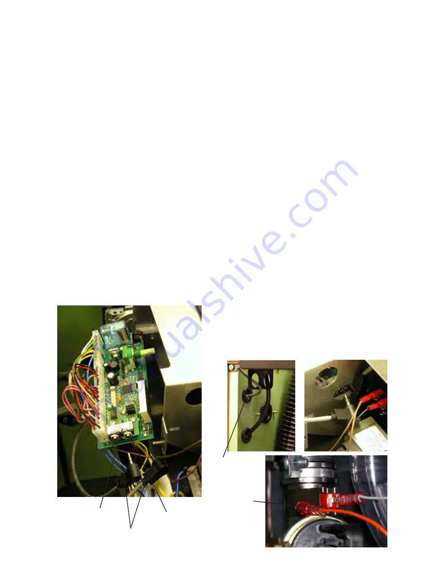
Multiple Heater Kit
Adapter PCB
Disconnected
Orange Wire
on Pool Temp
Sensor
(Slaves Only)
Connectors
Photo 2
Individual Part Numbers
1 per Heater,
M5160 Adapter PCB.
1 off per Installation
M5161, Terminator Plug, Red.
1 off per Installation,
M5162, Terminator Plug, Yellow
1 less than Heaters,
M5163, 4m Interconnection Cable
Overview
It is possible to connect together several Heaters
and by doing so obtain a larger output with an
economical and a fail-safe design. The Multiple
Heater Kit enables 2 or more Heaters to be con-
nected to obtain the necessary Load Sharing,
automatically. This works by one Heater being a
Master and the others being Slaves. The Master is
set for the required pool temperature and it then
controls as many of the Heaters as necessary to
obtain the temperature. It also equalises the running
time of every Heater so they all do the same amount
of work.
Condensing Pool Heater
17
14/11/06
Fig. 10.0
Installation Instructions
Disconnect the Heater from the Mains then
remove the Top Panel and the Electrical Chassis
Cover.
Remove Pool Thermostat Control Knob
Remove Pool Thermostat Board by removing
retaining plate and carefully slide out until fully
accessible. (
Fig. 10.0
)
Carefully fit the Adapter PCB in the space behind
the Pool Temp. Display on the Board (
Fig. 10.0
)
ensuring that the six pins on the Board pass
through the underside of the Adapter PCB
and, that the plastic locking pillars snap into
place. Refit Pool Thermostat Board and Knob.
Repeat steps 1) and 2) for all the Heaters.
Using the supplied cables, pass them through the
upper side panel grommet and daisy chain the
Heater Adapter PCBs together.(
Fig. 10.1)
The first
and last Heater in the ‘chain’ will use the Termina
tor Plugs
to fill their 2 unused sockets. There are
2 different coloured Terminators, they can go in
either the first or last Heater. NB. Ensure the
connectors are fully home (
Fig. 10.2)
Choose which Heater is to be the Master and
then make the rest Slaves by disconnecting their
Pool Temp Sensors. Remove the orange
connection to the Pool Temp Sensor located on
the rear heat exchanger connection (
Fig. 10.3)
Any external electrical control should only be
connected to the Master, Pool Demand.
Remove any Pool Demand links from the Slaves.
Turn on the Mains, then switch on all the
Heaters. After a short self-test the Master should
show the actual temperature, and the Slaves
three dashes “---”. If a Slave continues to show a
moving display of dashes this indicates it not
correctly connected to the Master, check the
Interconnection cable plugs are fully home.
Replace the panels.
Interconnection Cables
Fig. 10.1
Fig. 10.3
Fig. 10.2
Side Panel
Grommet


