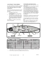
4:2 Installation Of Heater
Suggested procedure:
1. Position to suit system and terminal limitations.
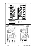
2. Mark & Drill Flue hole(s).
(see Fig. 4:8).
3. Remove the Electrical Tray and the Lower Case
from Heater module.
4. Plumb tails to pool, gas heating and hot water.
5. Test for leaks.
6. Replace the Lower Case and Electrical tray.
Space Required for Installation and Service.
Right or Left
30 mm
1 in.
Above
30mm
1 in.
Below
25mm
1 in.
In Front
450mm
18 in.
Table 3
4:3 Fixing the Heater
1. Position to suit system and terminal limitations.
2. Secure the frame, vertical, to the wall or floor
with the bracets provided..
3. Mark the wall or ceiling for the flue exit points
and core drill the wall to give a 0 to 3 degree
slope down towards the Heater. The recom-
mended core drill is 90mm for the Twin Pipe.
4:4 Terminal
The terminal can be fixed vertical or horizontal. The
flue pipe must always be connected to the extended
outlet of the terminal. The spacing is 120mm and a
core drill of 90mm is recommended.
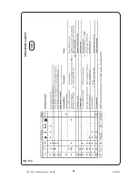
See Fig. 4:8
4:5 Twin Pipe Assembly
All the Twin Pipe components for this appliance are
lightweight plastic and utilise a push-fit system.
Very few fasteners are required and their use is
detailed on the instructions provided with the
components.
Important:
All Twin Pipe Installations must comply with the
following.
1. The Flue pipe must slope back to the Heater by
three degrees (1 in 20) on all horizontal runs. The
air pipe can be above or below horizontal.
2. Flue Pipes must be supported every 1000mm,
minimum.
3. All connections should be made with the Socket
end furthest from the heater.
4. Use the supplied CentraCerin or Silicone
Grease to ease the fitting of sections.
5. The combined Equivalent Length of Air and Flue
should not exceed 22m horizontal, or 30m
vertical and including any terminal parts.
6. The straight equivalent lengths of bends in a
horizontal design are as follows:
45 degrees, 1.3m.
90 degrees, 4m.
For more complex designs please see the details
provided with the components
It is recommended that:
1. That 45 degree bends are always used with
vertical flues and where possible used in prefer-
ence to 90 degree bends in horizontal installa-
tions.
2. Straight Flue pieces may be reduced in length
by cutting square. It will ease assembly if the
cut edge is cleaned, chamfered and greased
before insertion.
4:6 Plumbing
Prepare the flow and return pipe work on the base of
the Heater. If the requirement for Space Heating
exceeds 50,000 Btu/h (15kW), the Flow and Return
pipework from the Heater must be 28mm until the
heat load allows smaller bore pipework.
New pipework must be flushed through before
connecting.
4:7 Gas Connection
The 15mm gas connection point is provided. A
minimum of 20mb. (8in. w.g.) must be available at
the Heater inlet, with the Heater and other con-
nected appliances firing. Check for gas soundness
(B.S. 6891: 1988) in pipework to Heater using a
manometer. Open the gas cock. Gas soundness
within the Heater should be checked using sense of
smell and/or leak detection fluid. Check the burner
bar pressure with a manometer connected to the
control and adjust if required with the pressure
regulator.
10
100 Gas Condensing Pool Heater
01/06/02


