background image

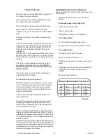
7:1:1  Control Fault Diagnostics

Before commencing a diagnosis it is recommended
that you familiarise yourself with the functions of
the Controls. These are detailed in the 

Users

Instructions Section 1:4 and in Heater Control,
Section 2:4  
The Control will diagnose and display
most of its own faults.

Self Check
The Control does a full self check during power up.
It also briefly lights all the LEDs and the Tempera-
ture Display so they can be checked for operation.

Demand Inputs
The front panel LEDs for Pool Demand and Heating
Demand are triggered from the Mains Inputs and the
chosen Priority. If they are not lit check the supplied
voltage, connections and Priority setting.

Relay Outputs
LEDs on the Control Board, beside the relays, are
directly connected to the relay outputs and show if
there is an output voltage to the Burner, Internal
Pump or Pool Pump. If they are not lit check the
output voltages, if correct replace the board. If lit,
check voltage at the component, replace if correct.

7:  FAULT FINDING
7:1 Heater Control

If the Heater fails to start, make the following checks.

1.

Is the mains electricity supply switched On?

2.

Is there a Demand for Pool or Space Heating?

3.

For Space Heating is the Heater Thermostat
set to the desired temperature?

6.

Check the fuses which should have been
fitted to the mains electricity supply to the
Timeswitch/Heater.  If the fuse has blown.
Replace it. If it blows again, call a Service
Engineer.

7.

Is the Filter LED lit? If it is, check Pool Pump
is running and the Filter is not blocked.

8.

Is the Overheat LED lit? If it is press the Reset
on the Control Panel.

If the fault is not permanently corrected by one of
these actions it is likely that a component is faulty
and will need replacing. This should only be carried
out by someone competent to do so.

IMPORTANT - E

LECTRICAL

 S

AFETY

I

T


IS


ESSENTIONAL


THAT


BEFORE


ANY


PANELS


ON


COMPONENTS

ARE


REMOVED


FROM


THE


HEATER

THAT


THE


MAINS


ISOLATOR


IS

SWITCHED


OFF

.

Displayed Faults
The Control board detects and displays certain fault
conditions. The display alternates between two
codes.

Display Reason

Action

Err / No

Control board fault.

Power Off then On
again. If not corrected

replace board.

Oc / thb

Boiler sensor

Check connections,

Open Circuit.

if correct, replace

sensor.

Oc / thp

Pool sensor

Check connections,

Open Circuit.

if correct, replace
sensor.

Sc / thb

Boiler sensor

Check connections,

Short Circuit.

if correct, replace
sensor.

Sc / thp

Pool sensor

Check connections,

Short Circuit.

if correct, replace

sensor.

Log
The Control keeps a log of the number of times the
Pressure Switch operates. These can be examined
and reset to zero in Setup Mode. The Temperature
Display units and Priority can also be checked and
altered in this mode.

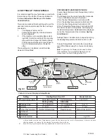
Setup Mode
To enter Setup Mode turn both temperature control
knobs to OFF.

The following must be carried out within 5 seconds.

To enter Setup Mode turn both Temperature Control
Knobs to OFF.
The following must be carried out within 5 seconds.
1. Turn on the Mains supply to the Heater.
2. Turn the Pool Temperature Control Knob ON.
3. Turn the Heating Temperature Control Knob ON.
4. Turn the Pool Temperature Control Knob OFF.
5. Turn The Heating Temperature Control Knob OFF.

The Control is now in ‘Setup Mode’ and displaying
the Heater temperature.
The Display can now show additional data as the
Pool Temperature Knob is rotated.


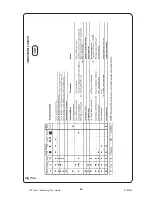
See Fig 7:1 and

Table 7:1

Settings that can be altered can be changed by
turning the Heating Temperature Control Knob On or
Off.

To leave ‘Setup Mode’ and retain the new settings,
turn off the Mains supply for a few seconds at any
time.

21

100 Gas Condensing Pool Heater

10/03/03

Summary of Contents for MBC100N

Page 1: ...7 WRc No 95 110 46 0087 Certikin 100 100W Condensing Pool Heaters Note to the Installer Natural gas Only Please leave these Instructions adjacent to the meter Installation Service User Instructions Model MBC100N MBC100NW Serial No ...

Page 2: ...er Valve 8 2 8 Safety Valve 8 2 9 Water to Water Heat Exchanger 8 2 10 Flow Regulator and Strainer 8 2 11 DHWTemperature Sensor 8 2 12 Removing the Case 8 2 13 Fan Assembly 8 2 14 Air Pressure Switch 8 2 15 FlueThermostat 8 2 16 Pump Overrun Thermostat 8 2 17 Control Sensor 8 2 18 Overheat Cut Off Device 8 2 19 Electrode and HT Lead 8 2 20 Pilot Assembly 8 2 21 Burner 8 2 22 Main Injector 8 2 23 C...

Page 3: ...d after 3 seconds Spa Setting for Spa Temperatures Required temperature is displayed when setting actual Spa Temperature displayed after 3 seconds NOTE The Heater is delivered set to display in Fahren heit For a Centigrade display see 6 3 Commissioning Section of Installation Instructions PoolTemperature Mechanical Stop Stop This can be used to obtain a repeatable setting and to limit maximum pool...

Page 4: ...upply then slowly open the Valve on the Base Panel until the Pressure Gauge shows 1 Bar Close both valves then disconnect the Filling Loop ON bar 0 4 2 1 3 user instructions inside user instructions inside 100 see instructions 1 6 Running the Pool Pump If this option has been installed the Heater can run the Pool Pump on its own Turn the Pool Tempera ture Control Knob to Pump just next to Off 1 7 ...

Page 5: ...The Manufacturer recommends this is prior to start ing the Heater each season 1 12Water Quality Chemical imbalance can cause severe damage to your Heater and associated equipment Maintain the pool water pH between 7 4 and 7 6 and ensure that the free chlorine levels are within the range recommended by the chemicals manufacturer for your size of pool Check the Filter regularly and keep the pool fre...

Page 6: ...ations as amended It is the law that all gas appliances are installed by a competent person e g a CORGI registered operative in accordance with the above Regula tions Failure to install appliances correctly could lead to prosecution It is in your own interest and that of safety to ensure that the law is complied with The installation of the Heater MUST also be in accordance with the current I E E ...

Page 7: ...osition MUST also permit the provision of a satisfactory balanced flue termination 3 This position MUST also permit the provision of a satisfactory connection to the condensate drain 2 3 If Combined With A Heating System The Controls provide a water temperature control for use with a heating system the Heating Demand Knob It requires an switched live from the Heating controls to be connected to He...

Page 8: ...maller size than the Heater inlet gas connection 3 FLUEING Detailed recommendations for flueing are given in BS 5440 1 The following notes are intended for general guidance 1 Be aware of the plume from the flue and the wetting effect it has to adjacent property 2 The flue can be taken upwards left right or to the rear of the appliance 3 The Heater is supplied with a Twin Pipe flue suitable for ter...

Page 9: ...le to produce the required flow rate see theTechnical Data New pipework must be flushed through before con necting The 100W incorporates a strainer and flow regulator set to 8 5 l m on the Cold Water Mains Inlet this can be removed in countries with warm climates The In let pressure should not exceed 10 bar a reducer should be fitted if it does Any hot water storage cylinder MUST be of the indirec...

Page 10: ... to 3 A More than 3 A Trip L N N T S HTR Permanent Live HTR Pool Demand Pool Pump Trip L N T S HTR Permanent Live Pool Pump Trip L N HTR Pool Demand DESIGN NOTES Takes full advantage of all the features of the Certikin Oil Pool Heater Pool Pump control providing overrun and Frost Protection action Provides the fastest installation Optional connections for Lights and Space Heating all provided 1 2 ...

Page 11: ...ry 1000mm minimum 3 All connections should be made with the Socket end furthest from the heater 4 Use the supplied CentraCerin or Silicone Grease to ease the fitting of sections 5 The combined Equivalent Length of Air and Flue should not exceed 22m horizontal or 30m vertical and including any terminal parts 6 The straight equivalent lengths of bends in a horizontal design are as follows 45 degrees...

Page 12: ...onnects to drain point on Flue SpigotAdapter Flue Spigot Adapter Drain Point Twin Pipe Heater Mounting Box Assembly Connects to condensate drain point on Condensate Drain Trap 11 100 Gas Condensing Pool Heater 01 06 02 PLAN VIEW FRONT VIEW Suggested fixings 3 into the floor OR 2 into the wall Fig 4 3 ...

Page 13: ...f and can only be inhibited by removing the Permanent Live supply to the Heater Thermostatic radiator valves can be used The Heater Pump is factory set at Speed 3 and should not be alterered The Heater waterside is completely copper so all good corrosion inhibitors are suitable Inhibitor is not required for Pool only applications The design temperature difference across the Heater for optimum oper...

Page 14: ...ve Drain From Pool Heating Flow Heating Return Fill Drain Condensate Drain To Pool Condensate Trap Pump Safety Valve Diverter Valve Auto Bypass Valve CW Inlet Three Way Valve Water to Water Heat Exchanger Filling Loop Pool Heat Exchanger Heat Exchanger Expansion Vessel Auto Air Vent HW Outlet 100W 100 Front View C L 100 Rear Flue Side View Twin pipe Maximum 22m horizontal 90mm 90 bend 4 0m 45 bend...

Page 15: ...Y G Y G Y B G Y V Gy Br R Or W Bk Gy V G Y B Brown Red Orange White Black Blue Grey Violet Green Yellow B L N Pressure Switch O H Pool Pump Heating Demand Pool Demand PUMP E N Lp CONTROL BOARD INTERNAL G Y E N N 250mA AS LRC POOL DMD HTG DMD HTR PUMP POOL PUMP BURNER Pressure Switch Burner Sensor Pool Sensor Common R R B Or Y Yellow W B Br B Gy V Sensor Pool 3 PORT VALVE BROWN RESET SWITCH Or Br L...

Page 16: ... G Y B G Y Spark Electrode 230 V Br Or Set Maximum CH Pressure 1 2 3 Fuse 315 mA Fuse 2 A P Pink Set Minimum CH pressure SWITCH 12 11 9 6 5 3 1 2 G Y 8 Br Cold 5 6 3 10k 10k SUPPLY E N L R Br R Or W Bk Gy V G Y B Brown Red Orange White Black Blue Grey Violet Green Yellow L N Pressure Switch O H Pool Pump Heating Demand Pool Demand CONTROL BOARD G Y N 250mA AS LRC POOL DMD HTG DMD HTR PUMP POOL PUM...

Page 17: ...e Filling Loop With the gas off run the heater to circulate the water and remove the air Turning the supply on and off will pulse the pump and help the air to rise to the Automatic Air Vent When completely clear of air re pressurise and remove filling loop Turn the gas back on The Heater is ready for use The Heater is fitted with automatic ignition and will start when the gas cock is open Mains is...

Page 18: ... system balance in the normal way to obtain even heating of all radiators If fitted set the cylinder thermostat to 60oC or lower if preferred Complete the Logbook and pass to the user when explaining and demonstrate the operation of the system Their instructions are in the first pages of this Installation Instructions Note The Heater is fitted with a syphon trap that in cludes a blocked drain dete...

Page 19: ...GAS VALVE Fig 6 2a 18 100 Gas Condensing Pool Heater 01 06 02 IN OUT GAS INLET GAS OUTLET INLET PRESSURE POINT OUTLET PRESSURE POINT GAS VALVE Fig 6 2b 100W 100 ...

Page 20: ... demand by turning On the Heating Temperature Control Knob Reset the log by turning the Heating Temperature Control Knob On or Off Table 6 3 Control Display in Setup Mode PROCEDURETO ENTER SETUP MODE To enter Setup Mode turn bothTemperature Control Knobs to OFF The following must be carried out within 5 seconds 1 Turn on the Mains supply to the Heater 2 Turn the PoolTemperature Control Knob ON 3 T...

Page 21: ...s above until proper adjustments is made Adjustment Knob NOTE If heater is installed outside of the limits shown below a flow switch must be used in place of thepressure switchwhenmountedandwiredadjacent to the heater TWO SPEED PUMPS Insomecases theflowonthelowspeedisinsufficient to operate the heater This is apparent when the pressure switch cannot be further adjusted or if the heater makes bangi...

Page 22: ...ulty and will need replacing This should only be carried out by someone competent to do so IMPORTANT ELECTRICAL SAFETY IT IS ESSENTIONAL THAT BEFORE ANY PANELS ON COMPONENTS ARE REMOVED FROM THE HEATER THAT THE MAINS ISOLATOR IS SWITCHED OFF Displayed Faults The Control board detects and displays certain fault conditions The display alternates between two codes Display Reason Action Err No Control...

Page 23: ...n or Off Fascia Indicator 1 Heater temperature Actual temperature Set temperature e g 20 70 Factory setting Alternative 2 Display Units F Fahrenheit C Centigrade C or F 3 Priority P Pool H Heating P or H 4 Filter Pressure log Number of Operations Resets to zero Yellow Filter LED On 5 Not used 6 Not used 7 Version Number _ _ e g 010 In this position with the Pool Temperature Control off the Heater ...

Page 24: ...e process Lamps on the edge of the Ignition Board indicate the stages in the ignition sequence Please refer to the lable inside the Heater Permanent live has to be connected to the L terminal then the Power lamp lights A call for heat powers the Ls terminal and the Running and Pump lamps light Provided the Flue Stat Overheat Stat and Heater are cold the fan starts up The pressure switch detects th...

Page 25: ...INDICATOR LIGHTS Fig 7 2a 24 100 Gas Condensing Pool Heater 01 06 02 100 ...

Page 26: ... ACTION Ensure Mains is ON Hot Water required required Turn on any Hot Water tap Ensure Clock Thermostat is set to call for heat Demand for heat Fan and Pump start For HW Diverter Valve moves to demand position Air Pressure switch detects air flow Burner lights on low flame Gas Valve opens for pilot Spark at electrode DHW Burner to full rate CH Low flame for 100 secs then increases to full rate Fl...

Page 27: ...rap or tubes Replace Electrode and Lead Replace the CVI board NO YES Replace the Pressure Switch YES YES Does the Burner light FAULT FINDING Hot Water Operation NO Is the Gas Inlet pressure 20 mb NO Provide adequate Gas Supply Replace CVI board problem solved if not replace CVI Valve YES Does Spark stop after Ignition NO YES YES Are the HT Lead Electrode OK Replace Electrode and Lead NO YES Replac...

Page 28: ...e OK Replace Electrode and Lead NO YES Replace CVI board Is polarity of Boiler supply OK NO YES Correct Does Burner Flame increase to Maximum Does the Flame reduce as temperature rises to Maximum Does the Flame reduce with the Boiler Thermostat Does the Flame stop before the O H trips YES YES YES YES Is the Thermistor reading correct to Table A NO NO NO NO Replace Thermistor NO YES Replace Main Bo...

Page 29: ...sate Syphon With a suitable bowl to catch the water unscrew the drain cap s on the underside of the Syphon Trap and drain the water Remove any solids and replace the cap s See Fig 10 3 8 2 Changing Components THERE ARE NO REPAIRABLE ITEMS IF NOT WORKING AN ITEM MUST BE REPLACED The Heater is in two major sections the Case and the Electrical Chassis The Major Components Diagram shows where the item...

Page 30: ...the CVI outlet connector and withdraw valve Re assembly is the reverse CVI Pressure Set Up Check Inlet pressure is at least 20 mbar when operating Remove the grey cover Remove one of the yellow leads from the Modureg and its grey plastic cover Attach a manometer to the outlet pressure tapping Set to Hot Water Only turn on a tap and check burner gas pressure is 1 8 mbar Adjust the 9mm brass nut on ...

Page 31: ...the Flow and Return connections Release the pressure in the boiler Unscrew the pressure sensor it may need a temporary plug to avoid leaks Re assembly is the reverse Fig 8 2 4 Replace unit with new or factory exchange unit Re assembly is the reverse ensure the fibre washers are in place 8 2 8 SafetyValve Remove the Electrical Tray Close the CH Flow and CH Return valves Drain the boiler through the...

Page 32: ...rmostat Re assembly using Heat Sink Compound is in the reverse order 8 2 17 Control Sensor Lower the Electrical Tray Remove the Case Unclip the sensor Pull the electrical connectors off the Control sensor Re assembly is the reverse 8 2 18 Overheat Cut off Device Lower the Electrical Tray Remove the Case To Reset Press Red Button Pull the electrical connectors off the Over heat Cut off device Unscr...

Page 33: ...the Case Remove the Front Baffle Remove the Combustion Chamber front by releasing the four screws Undo the Pilot tube from the Pilot Assembly and gently lever downwards away from the Pilot It has to be removed and replaced with the injector clipped into position Pull off the HT lead Pull the Burner forward off the two studs at the rear Remove the Pilot Assembly Re assembly is the reverse 8 2 22 Ma...

Page 34: ...eatThermostat Model 100W M0868 173068 Pilot Injector Model 100 7709 386 673 Pilot Injector Model 100W M0663 381656 Electrode Model 100 7710 386 744 16 HT Lead Assembly Model 100 M3895 17 Electrode Lead Model 100W M0666 Pilot Assembly Model 100 7716 381 865 Pilot Assembly Model 100W M0662 106437 18 FlueThermostat 7717 379 308 19 Clip on Sensor 22mm M3338 20 Clip on Sensor 15mm M3337 21 CondensateTr...

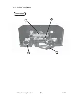
Page 35: ...34 100 Gas Condensing Pool Heater 20 10 03 9 2 Electrical Components 100 100W 16 6 9 8 ...

Page 36: ...10 DIAGRAMS 10 1 Major Components Fig 10 1 35 100 Gas Condensing Pool Heater 01 06 02 14 15 30 28 31 29 22 13 27 11 24 2 1 18 5 19 ...

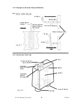
Page 37: ...Drain Soakaway Insulate against freezing 150mm Land Drain Filled with Gravel 750mm deep Condensate Drain from Heater Air Pressure Switch pipe connection Vent Syphon Connect To Waste Drain Cap Bypass 10 3 Condensate Drain Trap Note Internal minimum 19mm pipe External minimum 32mm pipe Condensate Drain for Twin Pipe Flue Fig 10 3 36 100 Gas Condensing Pool Heater 01 06 02 ...

Page 38: ...M4728 20 10 03 ...

Reviews: