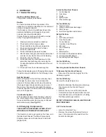
•
Examine the sealing strip for damage and
replace if necessary.
•
Place the Case somewhere safe from
damage
IMPORTANT: FAILURE TO CORRECTLY LOCATE
THE APPLIANCE CASE COULD RESULT IN
LEAKAGE OF COMBUSTION PRODUCTS
INTO THE ROOM.
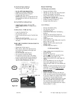
8.2.13 Fan Assembly
•
Lower the Electrical Tray.
•
Remove the Case.
•
Undo the wing nut holding the Fan Protection
Hoop.
•
Pull the electrical connectors off the Fan.
•
Gently pull the pressure tubing off the
tappings on the Flue Hood.
•
Undo the two screws holding the Flue Hood
and slide forward and away.
•
Re-assembly is the reverse.
8.2.14 Air Pressure Switch
•
Lower the Electrical Tray.
•
Remove the Case.
•
Pull the electrical connectors off the Air
Pressure Switch.
•
Gently pull the pressure tubing off the both
tappings on the switch.
•
Undo the M4 nut and wing nut holding the Air
Pressure Switch to its bracket on to the Back
Panel
•
Lift off its studs and rotate out of its bracket.
•
Re-assembly is the reverse.
8.2.15 Flue Thermostat
•
Lower the Electrical Tray.
•
Remove the Case.
•
To replace pull the electrical connectors off the
Flue Thermostat.
•
To reset press Red Button.
•
Re-assembly is the reverse.
8.2.16 Pump Overrun Thermostat
•
Remove the Electrical Tray.
•
Remove the Case.
•
Note the three wire colours and positions.
•
Pull the electrical connectors off the Pump
Overrun Thermostat.
•
Undo the two M4 screws holding the Thermostat.
•
Re-assembly using Heat Sink Compound is
in the reverse order.
8.2.17 Control Sensor
•
Lower the Electrical Tray.
•
Remove the Case.
•
Unclip the sensor.
•
Pull the electrical connectors off the Control
sensor.
•
Re-assembly is the reverse.
8.2.18 Overheat Cut-off Device
•
Lower the Electrical Tray.
•
Remove the Case.
(To Reset, Press Red Button)
•
Pull the electrical connectors off the Over
heat Cut-off device.
•
Unscrew from its mounting.
•
Re-assembly is the reverse.
•
Lower the Electrical Tray.
8.2.19 Electrode and HT Lead
•
Lower the Electrical Tray.
•
Remove the Case.
•
To Replace pull off the HT lead from the Control
Board/Sequence Controller.
•
Undo the left and right screws holding the
Front Burner Baffle.
•
Remove the front baffle.
For the 100 Only:
•
Release the tube nut holding the electrode to
the Pilot Burner.
•
Carefully withdraw the Electrode and HT
Lead.
For the 100W Only:
•
Push the Electrode towards the burner and
pull down and clear.
•
Re-assembly is the reverse.
8.2.20 Pilot Assembly
•
Lower the Electrical Tray.
•
Remove the Case.
•
Undo the left and right screws holding the
Front Burner Baffle and remove. If access is
restricted also remove the lower baffle.
•
Release the tube nut holding the electrode to
the Pilot Burner.
•
Undo the Pilot tube from the Pilot Assembly
and gently lever downwards away from the
Pilot. It has to be removed and replaced
with the injector clipped into position.
Undo the two screws retaining the Pilot
Assembly.
•
Re-assembly is the reverse
NB The pilot is not adjustable.
31
100 Gas Condensing Pool Heater
20/10/03

