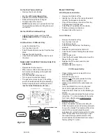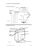
8.2.24 Combustion Chamber Insulation
•
Lower the Electrical Tray.
•
Remove the Case.
•
Remove the Front Baffle, then undo the four
M5 screws holding the lower baffle onto the
Back Panel
•
Remove the Burner, as in 10.
•
Undo the four screws holding the Chamber
to the Back Panel and lower downwards and
away.
•
Replace the Insulation Panels in the
Chamber.
•
Re-assembly is the reverse.
8.2.25 Primary Heat Exchanger
•
Lower the Electrical Tray.
•
Remove the Case.
•
Remove the front baffle.
•
Remove or cover the Burner.
•
Remove the Combustion Chamber.
•
Unclip the Control sensor.
•
Pull off the wires to the Overheat Cut Out
device.
•
Drain the Heater of water.
•
Undo the flow and return connections to the
Heat Exchanger and lower away.
•
Re-assembly is the reverse.
8.2.21 Burner
•
Lower the Electrical Tray.
•
Remove the Case.
•
Remove the Front Baffle.
•
Remove the Combustion Chamber front by
releasing the four screws.
•
Undo the Pilot tube from the Pilot Assembly
and gently lever downwards away from the
Pilot. It has to be removed and replaced with
the injector clipped into position.
•
Pull off the HT lead.
•
Pull the Burner forward off the two studs at
the rear.
•
Remove the Pilot Assembly.
•
Re-assembly is the reverse.
8.2.22 Main Injector
•
Lower the Electrical Tray.
•
Remove the Case.
•
Remove the Burner.
•
Undo the Main Injector from the manifold.
•
Re-assembly is the reverse.
8.2.26 Secondary Heat Exchanger
•
Lower the Electrical Tray.
•
Remove the Case.
•
Remove the Flue Thermostat.
•
Remove the Fan Assembly.
•
Drain the Heater of water.
•
Undo the flow and return connections to the
secondary Heat Exchanger.
•
Release the Condensate connection
clamping plate.
•
Undo the four screws holding the Secondary
Heat Exchanger to the Back Panel and lift
away.
•
Re-assembly is the reverse.
32
100 Gas Condensing Pool Heater
01/06/02


