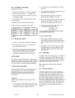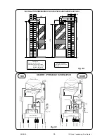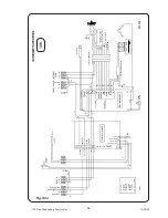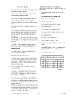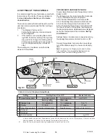
Terminal Position
Minimum
Below window or vent
300 mm
Below gutter or pipes
75 mm
Below eaves
200 mm
Below balcony or roof
200 mm
From a window
200 mm
From vertical pipe
75 mm
From corners
300 mm
Above ground, roof or balcony
300 mm
From facing surface
600 mm
From facing terminal
1200 mm
From opening under a car port
1200 mm
Vertically from a terminal
1500 mm
Horizontally from a terminal
300 mm
An Over Temperature Thermostat (Overheat).
Internal Pump control with run on.
Pool Pump control with run on and out-of-season
exercise. (Requires external contactor)
Pool Temperature and Setting display. Engineer
selectable °C or °F.
User Indicators for Pool, Heating, Overheat, and
Service.
Engineer indicators of all switched outputs for
simple diagnosis.
Priority selection of Pool or Heating, engineer
selectable.
Memory of: Filter occurrences.
Sensor failure detection and indication.
Control self checking with fault indication.
For more detail see the
Commissioning (6:1) an
Fault Finding (7:1) sections.
2:5 Gas Supply
The Local Gas Region should be consulted, at the
installation planning stage, in order to establish the
availability of an adequate supply of gas.
An existing service pipe must NOT be used without
prior consultation with the Local Gas Region, or by
a local Gas region contractor. An existing meter
should be checked preferably by the Gas region, to
ensure that the meter is adequate to deal with the
rate of gas supply required.
Installation pipes should be fitted in accordance
with BS.6891
Do NOT use pipes of a smaller size than the Heater
inlet gas connection.
3 FLUEING
Detailed recommendations for flueing are given in
BS.5440: 1. The following notes are intended for
general guidance.
1. Be aware of the plume from the flue and the
wetting effect it has to adjacent property.
2. The flue can be taken upwards, left, right or to
the rear of the appliance.
3. The Heater is supplied with a Twin Pipe flue
suitable for terminating on an outside wall 1
metre away. More complex and lengthy flues
are possible, please consult the Flue Application
Guide for designs and the components.
4. The Heater MUST be installed so that the
terminal is exposed to external air.
5. It is important that the terminal allows the free
passage of air across it at all times.
Table 1.
IMPORTANT.
It is absolutely ESSENTIAL to ensure, in practice,
that products of combustion discharging from the
terminal cannot re-enter the building, or any other
adjacent building, through ventilators, windows,
doors, other sources of natural air infiltration or
forced ventilation/air conditioning.
If this should occur, the appliance MUST be
turned OFF IMMEDIATELY and the Local Gas
Region consulted.
6. The acceptable spacing from the terminal to
obstructions and ventilation openings are
specified in Table 1.
7. Because the flue gases and terminal are at very
low temperature it is not necessary to fit a
Terminal guard to protect against burns. If a
guard is required for any other reason the
following is recommended.
For the Twin Flue Terminal:
Model B (black plastic coated).
For the Single Flue Terminal:
Model H (black plastic coated).
All are available from:
Tower Flue Components Ltd.
Tower House.
Vale Rise.
Tonbridge
KENT
TN9 1TB
01732 351555
7
100 Gas Condensing Pool Heater
01/06/02


