3:4 Sealed Systems
The Pool Heater is supplied with an Expansion
Vessel (see Technical Data for details), a Pressure
Gauge, a Safety Valve and Filling Loop following the
guidelines given in the Code of Practice BS 7074 :1.
Please check that the supplied Expansion Vessel is
adequate for the proposed system. The following
procedure is suggested.
1. Choose a vessel pressure by taking the static
head of the system, adding 0.3 bar, and taking
the nearest larger figure.
2. Select the Vessel Volume from the table below
by finding the System Volume and Vessel
Pressure.
3. Choose that size or larger from the manufactur-
ers’ range.
Vessel
System Volume
Litres
Pressure
50
60
70
100
150
Bar
Vessel Volume
0.5
4
4
8
8
12
1.0
8
8
8
12
18
1.5
8
12
12
18
24
Table 2.
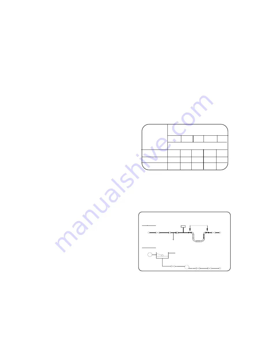
A design as detailed below should be used for the
filling connection, it utilises a BS 1010 stop valve, a
double non-return valve and filling loop fitted at low
level and should be installed with the approval of
the local Water Undertaking.
3:1 Air Supply
It is NOT necessary to have a purpose provided air
vent in the room or internal space in which the
Heater is installed.
Where the Heater is installed in a cupboard or
compartment no air vents are required. However the
User may wish to ensure that is ventilated to
provide air circulation.
3:2 Water Supply
The central heating system should be in accord-
ance with the relevant recommendations given in
BS.6798, BS 7593:1992 and, in addition, for
smallbore and microbore systems - BS.5449:1.
The domestic hot water system, if applicable,
should be in accordance with the relevant recom-
mendations of BS.5546.
Copper tubing to BS 2871:1 is recommended for
water carrying pipework.
The Mains Water supply should be clean and able to
produce the required flow rate, see the Technical Data.
New pipework must be flushed through before con-
necting.
The 100W incorporates a strainer and flow regulator
set to 8.5 l/m on the Cold Water Mains Inlet, this can
be removed in countries with warm climates. The In-
let pressure should not exceed 10 bar, a reducer should
be fitted if it does.
Any hot water storage cylinder MUST be of the
indirect type and should preferably be manufactured
of copper.
The hot water cylinder, & ancillary pipework, not
forming part of the useful heating surface should be
lagged, to prevent heat loss and any possible
freezing, particularly where pipes run through roof
spaces and ventilated underfloor spaces.
Draining taps MUST be located in accessible
positions, which permit the draining of the whole
system, including Heater and hot water storage
vessel. Draining taps should be at least ½ in.
nominal size and be in accordance with BS.2879.
3:3 Condensate Drain
Refer to Fig. 1:5, 5:1, and 10:2
A condensate drain is provided on the Heater, this
drain must be connected to the household drainage
point, or soakaway on site. All pipework and fittings
in the condensate drainage system MUST be made
of plastic. Refer to British Gas publication
“Guid-
ance notes for installation of domestic condensing
boilers”
The drain outlet on the Heater is :
Polypipe, 21.5mm pushfit overflow pipe.
ALTERNATIVE METHODS OF FILLING A SEALED
SYSTEM
Method A
Method B
Hose Unions
Air Inlet
Valve
Temporary Hose
Mains
Water
Supply
Mains
Water
Supply
Test Cock
Stop Valve
Drain &
Fill
Double
Check Valve
Assembly
Drain &
Fill
Cistern &
Overflow
Pressure
Pump &
Reducing
Valve If
Required
Stop Valve
3:5 Electricity Supply
Wiring external to the appliance MUST be in ac-
cordance with the current I.E.E. Wiring Regulations
and any Local Regulations that apply.
The Heater is supplied for 230V ~ 50Hz. Single phase.
Fuse rating is 3A.
Fig. 3:4
8
100 Gas Condensing Pool Heater
20/10/03


