SmaRT BU-x18XF and BU-xH18XF
U069.3.3
6
3.2
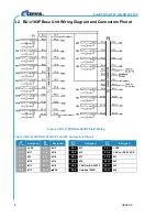
BU-x18XF Base Unit Wiring Diagram and Connectors Pinout
Figure 3. BU-x18XF/BU-xH18XF Field Wiring
Table 2. BU-x18XF/BU-xH18XF P1 and P2 Connectors Pinout
P1
Pin
Assigned
P1
Pin
Assigned
P2
Pin
Assigned
P2
Pin
Assigned
P1:1
+VDC
P1:7
M13
P2:1
M5
P2:7
+VDC
P1:2
M17
P1:8
M14
P2:2
M6
P2:8
CANL or RS-232 RX
P1:3
M9
P1:9
M15
P2:3
M7
P2:9
M1
P1:4
M10
P1:10
M16
P2:4
M8
P2:10
M2
P1:5
M11
P1:11
M18
P2:5
CANH or RS-232 TX
P2:11
M3
P1:6
M12
P1:12
VDC
P2:6
Umbilical PWR
P2:12
M4


