background image

900MHz Base Unit Manual 

2011 Cervis, Inc. 


13 


Visit our Web site at: 

www.cervisinc.com


 2011 Cervis, Inc. All rights reserved. Content is subject to change without notice. 


Summary of Contents for SmaRT BU-9H16AF-8F-8V-RS

Page 1: ...2011 Cervis Inc BU 9H16AF 8F 8V RS Base Unit User Manual DN U064 1 SmaRT_BU 9H16AF 8F 8V RS...

Page 2: ...l interference in a residential installation This equipment generates uses and can radiate radio frequency energy and if not installed and used in accordance with the instructions may cause harmful in...

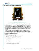
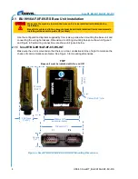
Page 3: ...2 1 4 SmaRT BU 9H16AF 8F 8V RS Wiring 7 3 0 Associate Mode 9 4 0 Available Options 10 5 0 Specifications 11 List of Figures Figure 1 SmaRT BU 9H16AF 8F 8V RS INT Base Unit 2 Figure 2 SmaRT BU 9H16AF...

Page 4: ...hen the button is pressed again SmaRT Base Unit I O unit to which the controlled machine is connected SmaRT base units communicate with each other and SmaRT handheld console and pistol grip remote con...

Page 5: ...moving the source power from the circuit Use a damp cloth to keep units clean Remove mud concrete dirt etc after use to prevent obstructing or clogging the buttons levers wiring and switches Do not in...

Page 6: ...effectively eliminates the risk of cross connections The rugged weatherproof enclosure allows the unit to operate worry free in harsh weather conditions The base unit provides a robust communication l...

Page 7: ...tes and a wide assortment of SmaRT Console Remotes For a full list of compatible SmaRT remote controllers please contact your Cervis Sales representative Communications between the BU 9H16AF 8F 8V RS...

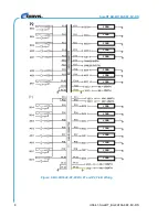
Page 8: ...base unit and connecting the wiring harnesses Dimensions for drilling mounting holes are shown in Figure 3 and Figure 4 Field wiring connections are shown in Figure 6 below 2 1 1 SmaRT BU 9H16AF 8F 8...

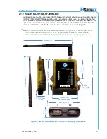
Page 9: ...to Heading 4 0 Available Options Installation of an extension antenna kit J5 07 3ft extension in our example is shown in Figure 5 Note The SmaRT BU 9H15AF EXT external antenna is hinged with 0 and 90...

Page 10: ...clear line of sight of the remote 1 Loosen and remove extension cable nut to allow the antenna ferrule to push through a mounting hole user discretion 2 Rethread the nut to secure the ferrule to the d...

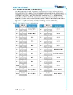
Page 11: ...or particular harness options Figure 6 is a simplified field wiring chart that indicates generic P1 and P2 wiring Table 1 BU 9H16AF P1 and P2 Cable Wiring Pin BB6 01 Signal Name Pin BB7 03 Signal Name...

Page 12: ...SmaRT BU 9H16AF 8F 8V RS U064 1 SmaRT_BU 9H16AF 8F 8V RS 8 Figure 6 BU 9H16AF 8F 8V RS P1 and P2 Field Wiring LOAD LOAD LOAD LOAD LOAD LOAD LOAD LOAD LOAD LOAD LOAD LOAD LOAD LOAD LOAD LOAD...

Page 13: ...ote used while in Associate mode will vary depending on the type of SmaRT remote with which the base unit is to communicate Please reference the appropriate SmaRT remote control manual Cervis Engineer...

Page 14: ...representative Table 2 Available Options Part Number Description BB6 01 HN 1001 gray 12 conductor cable harness 36 inches in length BB7 03 HN 1002 black 12 conductor cable harness 36 inches in length...

Page 15: ...o 100 Indicators 12 Status WINK Needs Upgrade SLOW Normal FAST No Association ON Link Lost Serial ON Active Radio RX ON Active Radio TX ON Active Error ON Error Digital Out ON Active Digital In ON Act...

Page 16: ...SmaRT BU 9H16AF 8F 8V RS U064 1 SmaRT_BU 9H16AF 8F 8V RS 12...

Page 17: ...900MHz Base Unit Manual 2011 Cervis Inc 13 Visit our Web site at www cervisinc com 2011 Cervis Inc All rights reserved Content is subject to change without notice...

Reviews: