SmaRT BU-xH6R
U078.2.3-SmaRTxH6R_BU-R
6
1.3
BU-xH6R Wiring
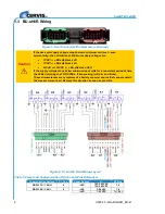
Figure 5. Dual Connectors/Pin Numbers (enhanced)
Caution
If the base unit supply voltage drops below a minimum volt level
—even
momentarily
—the unit will reset. Minimum supply voltages are:
7VDC for a BU-xH6R-xxx-LVD
7VAC for a BU-xH6R-xxx-LVA
90VAC or 100VDC for a BU-xH6R-xxx-HVU
If the supply voltage drops below minimum input volts for a consistent period of time,
the LEDs (including the TX/RX LEDs, if transceiving) will dim and flicker.
These circumstances are symptoms of a battery or power source that cannot sustain
the present current load. Remedy this situation as soon as possible.
Figure 6. P1 and P2 Field Wiring Layout
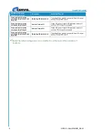
Table 1. Power and Communication Options and Pins References
Communication Options
P1 Pins
Power Options
V
in
P2 Pins
RS-232 TX / CAN H
4
–HVU
100
–240 VAC
120
–340 VDC
7, 9
RS-232 RX / CAN L
5
–LVA
7
–28 VAC
7, 8
–LVD
7
–32 VDC
7(-), 8(+)
P1
P2


