background image

SmaRT Console Box Remote 


©

2020 Cervis, Inc. 

2.2 

CB-xH Battery Installation and Replacement 

The SmaRT console box remote operates between 1.9 to 3.2 VDC powered by two 1.5 V type 
“C” cell batteries (included when shipped). Nominal battery life expectation is approximately 70 
to 100 operating hours

1

 before it becomes necessary to replace the batteries. 


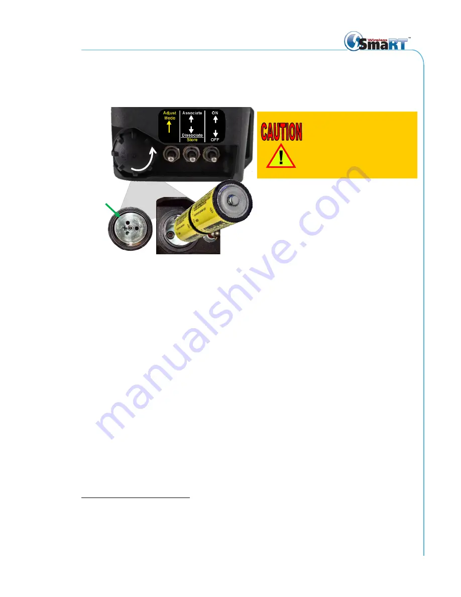
Figure 3. SmaRT Console Box Battery Installation 

Battery Replacement Process 

1.  Remove the battery cover by unscrewing it in the counter-clockwise direction. 

2.  Remove the discharged batteries and properly dispose of them according to local 

regulations. 

3.  Place two 

“C” cell batteries in the terminal cavity. Observe proper polarity, with 

the negative side inserted first and each positive battery terminal facing toward 
the cap. The + polarity marking is cut in the interior of the cap as illustrated in 
Figure 3. 

Replace the battery cover by threading it clockwise onto the cavity. You will feel tension as you 
tighten the cap. Hand-tighten the cap to compress the compartment O-ring seal embedded in 
the cap. Make sure you do not overtighten the cap, or you will damage the battery compartment. 

Note: Change batteries soon after the first low-battery warning to ensure continued reliable 

operation. Cervis, Inc. recommends having fresh spare batteries on hand at all times that the 
system is in use. The console box remote senses when the voltage is at the low power 
threshold

—approximately 2.1 V—at which time, the Amber battery (BATT) LED periodically 

flashes to warn you that you must change the batteries soon. The warning flashes while the 
unit is in use either until the batteries are replaced or until the voltage drops below 1.9 V; after 
which, the unit automatically powers down (auto-shutdown). The unit will not power-up and 
operate until the depleted batteries are replaced. Cervis, Inc. recommends replacing them 
with two fresh batteries. 


1

  At room temperature. Not only does usage affect battery life, but so does operating or storing the battery in 

too-high or too-low ambient temperatures. For instance, the longer batteries are exposed to extreme cold or 
heat, the more likely battery life will be negatively affected. Factors such as a battery

’s age and initial quality 

also may come into play. 


Observe proper polarity when 
placing batteries into the 
battery compartment. Improper 
battery placement can cause 
excessive heat, battery 
explosion, injury to the 
operator, and damage to the 
remote. 

Two 

“C” Cell Batteries 

OPEN 

Battery 

Compartment 

Gasket 

Seal  

+

 (Positive) 

Summary of Contents for SmaRT CB-xH

Page 1: ... 2020 Cervis Inc Console Box Remotes CB xH Manual U093 3 0 ...

Page 2: ...xempt RSS standard s Operation is subject to the following two conditions 1 this device may not cause interference and 2 this device must accept any interference including interference that may cause undesired operation of the device Le présent appareil est conforme aux CNR d Industrie Canada applicables aux appareils radio exempts de licence L exploitation est autorisée aux deux conditions suivan...

Page 3: ... Off 9 2 6 Associate Console Box with System Base Unit 10 2 7 Dissociate Console Box from System Base Unit 11 2 8 Proportional Output Lever and Joystick Adjustments 12 2 8 1 Enter Adjust Mode for Standard Base Unit PWM Outputs 12 2 8 2 Minimum Adjustment 13 2 8 3 Maximum Adjustment 13 2 8 4 Enter Adjust Mode for Enlarged Base Unit EBU PWM Outputs 14 2 8 5 Minimum Adjustment 14 2 8 6 Maximum Adjust...

Page 4: ...nit 11 Figure 6 Enter Lever or Joystick Adjust Mode Standard Base Unit 12 Figure 7 Enter Lever or Joystick Adjust Mode EBU 14 Figure 8 Umbilical Connection Option and C4 20 Umbilical Kit Example 16 Figure 9 Agency Identification Label Locations 19 List of Tables Table 1 CB xH Remote LEDs 4 Table 2 CB xH Remote Operational LED Diagnostic Information 4 Table 3 CB xH Remote Console Box Specifications...

Page 5: ... Use a damp cloth to keep units clean Remove mud concrete dirt etc after use to prevent obstructing or clogging the buttons levers joysticks wiring and switches Do not allow liquid to enter the handheld or base unit enclosures Do not use high pressure equipment to clean the handheld remote or base unit Disconnect the radio base unit before welding on the machine Failure to disconnect the base unit...

Page 6: ... base units either standard or enlarged sizes the CB remote s ergonomic layout offers comfortable SmaRT system operation The SmaRT CB xH also offers a variety of joystick and switch options several of which are illustrated in Figure 1 that are factory configured to order The controllers provide a robust link with SmaRT base units in congested radio environments allowing seamless association withou...

Page 7: ...eck and up to three toggle switches on either side for a possible total of 17 toggle switches A variety of pushbuttons potentiometers and rotary switches design dependent Choice of stop switch twist up or pull up Umbilical cable option available for backup or network control area network CAN control Branding Labeling Option Cervis Inc offers in house design of attractive custom labels for engineer...

Page 8: ...nt L2 Receive RX Amber Flashes when message is received L3 Error ERR Red Lights when error occurs L4 Battery BATT Amber Low battery warning when on 2 1 V L5 L8 Custom Amber Custom optional Table 2 CB xH Remote Operational LED Diagnostic Information Condition LED Information Console Box Is Transmitting Switch Active On Console Box TX rapid blinking TX solid Low Battery BATT slow blinking M Stop Sto...

Page 9: ...atteries soon after the first low battery warning to ensure continued reliable operation Cervis Inc recommends having fresh spare batteries on hand at all times that the system is in use The console box remote senses when the voltage is at the low power threshold approximately 2 1 V at which time the Amber battery BATT LED periodically flashes to warn you that you must change the batteries soon Th...

Page 10: ...ase fasteners keep a single CB xH securely against your body Plus its polypropylene webbing resists wear and its bright orange color gives it high visibility against even the lightest colored garments 2 3 1 Adjusting the Harness Before you attach the harness to your CB xH adjust the blue strap to the most comfortable operating length for your individual body type The harness left strap features a ...

Page 11: ...ds of the high visibility orange straps feature a pair of heavy duty metal button snaps at the ends To attach the harness to your CB xH locate either the two T shaped harness clips on the front of your CB one is on the left side the other is on the right or the orange bar across the top of it ...

Page 12: ...ibility orange straps through the harness mounts or bar snap side up past the first two female snaps Fold the strap over onto itself and fasten the female snaps to their male counterparts Note You ll know the snaps are secured when you hear a clicking sound ...

Page 13: ...ws 1 Stop Button a Twist up Stop button Release the Stop button by twisting clockwise until it pops up spring loaded b Pull up Stop button Pull the Stop button up 2 Flip the ON OFF switch S12 UP and hold it until the LEDs activate 2 5 Turn CB xH Remote Off Shut down the console box remote using any of the following methods Push the Stop switch down for immediate stop Flip the ON OFF switch S12 DOW...

Page 14: ...be OFF and the base unit must have power disconnected Associate with the Base Unit 1 Stand near the base unit with the CB remote OFF and power removed from the base unit that is either detach cables from the base unit or disconnect the power source 2 Release the Stop switch twist up or pull up on the remote 3 Hold the Associate switch S13 UP While holding the Associate switch UP activate the CB re...

Page 15: ... box remote OFF and power removed from the base unit that is either detach cables from the base unit or disconnect the power source 2 Release the Stop switch on the remote 3 Hold the Dissociate switch S13 DOWN While holding the Dissociate switch DOWN activate the console remote by holding the ON OFF switch S12 UP Continue to hold both switches 4 When the TX LED blinks once per second apply power t...

Page 16: ...sets to ten seconds each time a lever or joystick is operated while in Adjust Mode Adjust each Pulse Width Modulation PWM lever or joystick using the following steps Each lever or joystick direction can be independently adjusted Figure 6 Enter Lever or Joystick Adjust Mode Standard Base Unit 2 8 1 Enter Adjust Mode for Standard Base Unit PWM Outputs 1 Release the Stop switch twist up or pull up an...

Page 17: ... set maximum lever or joystick activation 2 8 3 Maximum Adjustment LED 7 on the standard base unit lights solid see right indicating Select Mode maximum 1 To select the maximum activation of the lever or joystick to be adjusted move the desired lever or joystick beyond 50 deflection and release it back to neutral LED 7 on the standard base unit flashes indicating Adjust Mode max To retain the curr...

Page 18: ...lever or joystick beyond 50 deflection and release back to neutral LED 3 on the EBU flashes indicating Adjust Mode Min To retain the current minimum value flip the Adjust switch S14 UP To set the minimum to 0 flip the Associate switch S13 DOWN to store that value To adjust the current value slowly move the lever or joystick again until machine movement is initiated Continue to hold in position and...

Page 19: ... to Select Mode Max allow the lever or joystick to return to neutral LED 2 on the base unit will light solid 2 LED 3 will go out and LED 2 will light solid after storing indicating a return to Select Mode Min Return to Section 2 8 5 to set minimum lever activation Note Activating the Associate S13 DOWN and the Adjust switch S14 UP will toggle between MIN and MAX while in Adjust Mode 2 8 7 Exit Adj...

Page 20: ...ds are issued to the base unit through the umbilical cable Cervis Inc offers an array of umbilical kits that simplify connecting a SmaRT console box Figure 8 illustrates an example of a C4 20 Umbilical Kit that may be used in a SmaRT console box system Figure 8 Umbilical Connection Option and C4 20 Umbilical Kit Example Umbilical Power 7 V 32 V Base unit connections are determined by the specific ...

Page 21: ...hing on transmit RX amber Flashing on receive ERR red Solid Error BATT amber Slow Blinks below 2 1 V warning approaching discharge replace batteries L5 amber L6 amber L7 amber L8 amber Custom LED color optional Custom LED color optional Custom LED color optional Custom LED color optional Enclosure Dimensions 263 5 mm x 141 5 mm x 139 mm 10 4 x 5 6 x 5 5 Durability High impact glass filled polymer ...

Page 22: ...a belt or harness Equipment containing the radio module was evaluated for RF exposure hazards by two approaches 1 Maximum Permissible Exposure MPE for mobile applications 2 Specific Absorption Rate SAR for portable applications Required separation distances are measured from the actual location of the radiated part of the antenna An antenna may be inside the host application affixed to the enclosu...

Page 23: ... Remote 2020 Cervis Inc 19 Appendix C Agency Identification Label Location Figure 9 Agency Identification Label Locations Note The Agency ID label for all console boxes can be found in the position shown Agency ID Label ...

Page 24: ...del Specific Features Model Name Freq RF Power Proportional Inputs Prop Input Type Umbilical CB 9H07LV 900 MHz 10 mW 7 Single Axis Levers No CB 9H07LV UMB 900 MHz 10 mW 7 Single Axis Levers Yes CB 2H07LV 2 4 GHz 100 mW 7 Single Axis Levers No CB 2H07LV UMB 2 4 GHz 100 mW 7 Single Axis Levers Yes CB 9H03JS 900 MHz 10 mW 3 Dual Axis Joysticks No CB 9H03JS UMB 900 MHz 10 mW 3 Dual Axis Joysticks Yes ...

Page 25: ...SmaRT Console Box Remote 2020 Cervis Inc 21 Visit our Web site at www cervisinc com 2020 Cervis Inc All rights reserved Content is subject to change without notice ...

Reviews: