background image


SmaRT DIN-9H1R5 


U082.0.2 DIN-9H1R5 

1.0 

SmaRT DIN-9H1R5 Base Unit 

The SmaRT DIN-9H1R5 Base Unit for industrial control systems features one Form C and five 
Form A relay outputs. Each Form C relay contact can switch a resistive load of 10 A max. @ 
250 VAC/30 VDC. Each Form A is rated at 5 A max @ 250 VAC/30 VDC resistive load and 2 A 
max @ 250 VAC/30 VDC inductive load. Using Channel-Hopping Direct Sequence Spread 
Spectrum (CH DSSS) wireless technology at 900 MHz, the base unit provides a robust link with 
a handheld remote in congested radio environments at extended ranges. The SmaRT base unit 
enclosure allows it to be mounted either horizontally or vertically to a standard 35mm DIN rail. 
Four status/diagnostic LEDs

—as shown in Figure 1—determine the state of the unit.  


Figure 1. DIN-9H1R5-INT and DIN-9H1R5-EXT LEDs 

DIN-9H1R5 Base Unit Features 


Input power +7 to +32 VDC 


900 MHz Channel-Hopping Direct Sequence Spread Spectrum (DSSS) Technology 


Internal or external antenna 


1 Form C Relay Contact output; 5 Form A Relay Contact outputs  


DIN enclosure with screw terminal connections  


Can be mounted horizontally or vertically on a standard 35-mm DIN rail 


Size M3 (flat or Phillips) screw terminals 


Four LED diagnostic indicators 


Compact design, durable UL94V-0 rated ABS plastic enclosure 

Green pulse/sec 

– Health OK 

Green when any output is active 

TX/RX 

– Amber while transceiving 

POWER 

– Red OK 

DIN-9H1R5-INT 

DIN-9H1R5-EXT 

Summary of Contents for SmaRT DIN-9H1R5

Page 1: ...2020 Cervis Inc SmaRT DIN 9H1R5 Base Unit User Manual U082 0 2 DIN 9H1R5...

Page 2: ...s website https www canada ca en health canada services environmental workplace health reports publications radiation safety code 6 health canada radiofrequency exposure guidelines environmental work...

Page 3: ...9H1R5 CB Remote Communication 11 C3 DIN 9H1R5 MCB Remote Communication 13 C4 DIN 9H1R5 PG Remote Communication 15 C5 DIN 9H1R5 XX 218 Remote Communication 16 List of Figures Figure 1 DIN 9H1R5 INT and...

Page 4: ...5 Base unit with six relay outputs controlled by a SmaRT handheld remote Each SmaRT DIN 9H1R5 can communicate with up to eight SmaRT remote control units A DIN 9H1R5 can be mounted on a standard 35 mm...

Page 5: ...te the remote control system until certain that it is safe to do so Turn off the handheld remote and remove power from the base unit before attempting any maintenance This will prevent accidental oper...

Page 6: ...ws it to be mounted either horizontally or vertically to a standard 35mm DIN rail Four status diagnostic LEDs as shown in Figure 1 determine the state of the unit Figure 1 DIN 9H1R5 INT and DIN 9H1R5...

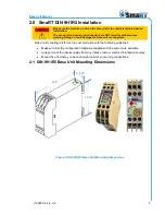
Page 7: ...ge the base unit or connectors Base unit mounting is left much to your discretion with the following guidelines Make sure that the configuration diagrams supplied with the system are available Always...

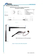
Page 8: ...SmaRT DIN 9H1R5 U082 0 2 DIN 9H1R5 4 2 2 External Antenna Mounting Figure 3 External Antenna Mounting Details BB3 06 900 MHz Antenna and AA7 07 Extension Adapter 183 mm 7 2 212 mm 8 35...

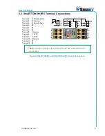
Page 9: ...5 K1 Common Terminal 4 K1 Normally Open Terminal 3 K6 Terminal 2 K5 Terminal 1 K4 Terminal 9 K Common Terminal 8 12 VDC Terminal 7 12 VDC Terminal 12 K Common Terminal 11 K3 Terminal 10 K2 1 2 3 4 5...

Page 10: ...ishing the communications link between the system remote control unit and the base unit If you have a customized system and need to Associate or Dissociate refer to the custom Engineered System Manual...

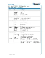
Page 11: ...c OK Red or Amber Pulse sec Fault TX RX Green Transmit Red Receive Power Red OK Enclosure Dimensions 22 6 mm x 82 mm x 99 mm 0 89 x 3 23 x 3 90 Durability Durable UL94V 0 rated ABS plastic Mounting We...

Page 12: ...ing an external antenna should be mounted to ensure the antenna is at least 20cm away from the human body Only the external antenna recommended by Cervis Inc is to be used see Table 2 Appendix B Agenc...

Page 13: ...om the base unit memory The Associate procedure must be used by any handheld that now needs to control that DIN 9H1R5 The following Associate and Dissociate procedures are general methods of associati...

Page 14: ...d in your hand 3 Press and hold both Associate Button 1 and Dissociate Button 2 see Figure 6 The RX and ER LEDs light 4 Continue to hold both buttons until the TX and RX LEDs light steady 5 When TX an...

Page 15: ...up the base unit while continuing to hold S13 and S12 When the TX RX ERR and BAT LEDs light solid release S13 and S12 A successful association is indicated when LEDs TX and RX are rapidly blinking in...

Page 16: ...SmaRT DIN 9H1R5 U082 0 2 DIN 9H1R5 12 Note Be aware that all remote associations to the base unit are now broken...

Page 17: ...be in the UP position before activating and using the MCB remote 1 Stand near the base unit with the remote OFF and power removed from the base unit disconnect P1 and P2 or turn the source power OFF 2...

Page 18: ...th the remote OFF and power removed from the base unit disconnect P1 and P2 or turn the source power OFF 2 Release the STOP button on the MCB remote by pulling up 3 Push and hold switch S1 DOWN and th...

Page 19: ...nit while continuing to hold S1 and S7 When all four LEDs light solid release S1 and S7 Association is successful when LEDs TX and RX are rapidly blinking in unison Figure 9 PG Switch Actuation for As...

Page 20: ...dicated when none of the LEDs are active when any function button is pressed Safely power down the SmaRT base unit by disconnecting the power source from the unit Figure 10 XX 218 Associate Mode Note...

Page 21: ...dheld in a clear unobstructed line of sight 3 Press and hold button 2 then press and hold button 1 Hold both buttons simultaneously 4 Wait until the amber LED2 goes out Release the two buttons being h...

Page 22: ...SmaRT DIN 9H1R5 U082 0 2 DIN 9H1R5 18 Visit our Web site at www cervisinc com 2020 Cervis Inc All rights reserved Content is subject to change without notice...

Reviews: