background image


User Manual 


U129.0.0 

2.0  How to Associate a Transmitter to a Receiver 

Warrior transmitters are associated (or paired) with the receiver at the factory before the system 
is shipped. A receiver will only communicate with the transmitters it is associated with.  

In the event that you need to ‘move’ a transmitter from one crane to another or put a spare 
transmitter into service with a receiver it is not associated to the association process is the 
procedure to accomplish this working link.   

You may refer to the following receiver manual for additional information if 
necessary.   

U104 Warrior MU-9X15 Receiver Manual 

      The process 

All Warrior systems use a first come first serve protocol standard meaning more than one 
handheld can be associated with a receiver but only one can be in control of the receiver at a 
time.  To clear a transmitters memory such that it is not associated to a receiver refer to section 
2.1.     

Note: Before attempting association, make sure that receiver S01 DIP Switch #8 in the 

desired receiver is set to the ON (1) position. 


1.  Follow start-up procedure steps 1, release STOP switch 


2.  When the 

B LED

 is 

ON

 solid, simultaneously press and release the 

A/B Select 

and WARNING/START

 switches.   


The four LEDs will begin to ‘scroll’ from bottom to top (B, A, Battery, TX/RX) 

indicating you are now in the transmitters ‘Maintenance Mode’.   

Note

: If the B LED goes out before you press the buttons, restart the process 


3.  Now press and hold 

Hoist UP

 and 

Hoist DOWN

 buttons for five seconds or until 

LED A begins blinking.  Once LED A is blinking release the buttons. 


The transmitter is now in Association Mode and begins scanning the area for  

receivers that are ‘unlocked’ and are available to be associated to.  During this  

process the transmitter will compile a list of the available receivers.  Once this 

 process is complete the A LED will go out and the B LED will come ON and the  

first receiver in the LIST will begin activating its HORN/ASSOCIATION relay  

telling you it can be selected.   


1


0


Summary of Contents for Warrior ETHOS HHMS-9XW08-ND

Page 1: ...2020 Cervis Inc ETHOS HHMS 9XW08 ND Model Transmitter Manual...

Page 2: ...code 6 health canada radiofrequency exposure guidelines environmental workplace health health canada html Industry Canada Statement This device complies with Industry Canada licence exempt RSS standa...

Page 3: ...r 6 2 1 Celaring a transmitters memory Error Bookmark not defined 3 0 Transmitter Specifications 10 Appendix A Exposure to Radio Frequency Energy 11 Appendix B RF Exposure Considerations 11 Appendix C...

Page 4: ...mote control system until certain that it is safe to do so Turn off the transmitter and disconnect power from the receiver before attempting any maintenance This will prevent accidental operation of t...

Page 5: ...sion IEC standard 60529 The unit has four diagnostic LEDs that indicate radio frequency RF transmit receive Battery status and A selection and B selection Frequency Channel Hopping Direct Sequence Spr...

Page 6: ...Indication Meaning 1 Radio Frequency RF ON Transmitter searching for receiver or a button is being pressed Flashing Transmitting and receiving messages communicating with a receiver If a lag is occur...

Page 7: ...into the transmitter body until you hear a click Note Make sure the battery contacts are positioned relative to the front right side of the transmitter To charge the battery pack 1 Pinch the clamps o...

Page 8: ...ack The LED continues to flash until the voltage level drops to 6 1V when Auto Shutdown occurs Note The receiver LED quickly flashes three times once per minute when transmitter low battery is indicat...

Page 9: ...or main contactor closes Note If the Radio TX RX LED is on solid once you release the STOP switch the handheld may not be associated to a receiver or the receiver it is associated to may not have powe...

Page 10: ...refer to section 2 1 Note Before attempting association make sure that receiver S01 DIP Switch 8 in the desired receiver is set to the ON 1 position 1 Follow start up procedure steps 1 release STOP s...

Page 11: ...T switch make the selection If this is not the desired receiver continue to press and release the A B Select until the desired receiver is indicating it can be selected Again once the desired receiver...

Page 12: ...e Mode Note If the B LED goes out before you press the buttons restart the process 3 Now simultaneously press and hold Hoist UP Hoist Down While holding UP and DOWN press Trolley Reverse and release a...

Page 13: ...ETHOS Model Transmitter 2020 Cervis Inc 9...

Page 14: ...to 60 C Storage Temp 22 F to 158 F 20 C to 70 C Humidity 0 95 non condensing Radio Frequency 904 926 MHz 100mW License No license required Modulation DSSS Antenna Internal Enclosure Dimensions 76 2mm...

Page 15: ...r a belt or harness on the torso Equipment containing the radio module was evaluated for RF exposure hazards by two approaches 1 Maximum Permissible Exposure MPE for mobile applications 2 Specific Abs...

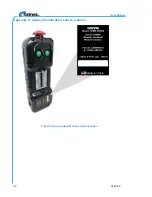
Page 16: ...User Manual U129 0 0 12 Appendix C Agency Identification Label Locations Figure 5 Agency Identification Label Locations...

Page 17: ...ETHOS Model Transmitter 2020 Cervis Inc 13 Visit our Web site at www cervisinc com 2019 Cervis Inc All rights reserved Content is subject to change without notice...

Reviews: