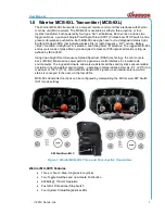
background image

User Manual 

2019


Cervis, Inc. 

15 

The 

RF

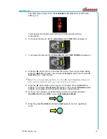
 LED starts blinking rapidly, indicating communication is established. The 

selected receiver ID is stored in the MCB memory slot. 


10.  Press the green 

Horn/Start

 pushbutton (

S09

) to pull in the MLC relay.  


The MCB is now linked to the chosen receiver, and the crane is ready for control. 

Notes


Associate each MCB transmitter one-at-a-time. Once associated, the transmitter will only 
work with that receiver until its ID is cleared. 


Transmitters work on a first-come/first-serve basis, meaning only one transmitter can ever 
be paired to a chosen receiver at a time. 


If you purchase a spare transmitter, you will have to associate it using the association 
process described above. 


Transmitters for each newly purchased system are associated at Cervis, Inc. before 
shipping. 

4.3 

Adjusting MCB-9XL Inactivity Timeout 

The Warrior MCB-9XL ships from the factory configured with a standard four-minute inactivity 
timeout. To adjust the timeout interval length

—from one minute to infinity (or no timeout)—in the 

field, follow these steps. 

1.  Confirm that the

 STOP

 switch is pressed 

DOWN


2.  Press and release the green 

Horn/Start

 pushbutton (

S09

) to turn on the MCB.  


The 

B Selection

 LED lights steadily. 


Summary of Contents for Warrior MCB-9XL

Page 1: ...2019 Cervis Inc MCB 9XL Transmitters U106 3 0...

Page 2: ...ant les limites de Sant Canada pour la population g n rale consulter le Code de s curit 6 disponible aupr s de Sant Canada site Web https www canada ca en health canada services environmental workplac...

Page 3: ...2 1 Associating an MCB 9XL Using the DIP Switch Unlock Method 11 4 2 2 Associate an MCB 9XL to a Receiver 12 4 3 Adjusting MCB 9XL Inactivity Timeout 15 4 4 Tilt Fault Mode 18 5 0 Warrior MCB 9XL Spe...

Page 4: ...i console box transmitter and remove power from the machine unit before attempting any maintenance This will prevent accidental operation of the controlled machinery Use a damp cloth to keep units cle...

Page 5: ...meet an IP55 ingress protection rating as defined by IEC 60529 Using line of sight Direct Sequence Spread Spectrum DSSS technology the mini console box s MCB s transmission power permits a generous c...

Page 6: ...Warrior MCB 9XL Transmitters U106 3 0 2 Operates Using Four AA Cell Batteries Mounting by Custom Shoulder Harness...

Page 7: ...tained Pull up to ENABLE Push down to STOP 2 2 LEDs Table 2 lists the MCB 9XL LEDs Table 3 lists advanced LED diagnostic functions Table 2 MCB 9XL LEDs LED Icon Function Action L1 Transmit indication...

Page 8: ...ng level unit shutting down replace batteries with fresh set A B Shutting Off Joystick Lever command reached out of bounds Condition unsafe operation turning off 2 3 Neck Shoulder Harness The 1 wide n...

Page 9: ...ngth for your individual body type The harness left strap features a 6 152mm long quick release hook and loop Nylon rip cord Connect the two parts of the rip cord together and press down to secure the...

Page 10: ...s U106 3 0 6 To attach the harness to your MCB 9XL locate the two T shaped harness clips on the front of your MCB Thread the high visibility orange straps through the harness mounts snap side up past...

Page 11: ...User Manual 2019 Cervis Inc 7 Fold the strap over onto itself and fasten the female snaps to their male counterparts Note You ll know the snaps are secured when you hear a clicking sound...

Page 12: ...Warrior MCB 9XL Transmitters U106 3 0 8 When you have the harness securely together hang it around your neck or drape it over your shoulder and begin operating your MCB 9XL...

Page 13: ...ompartment 3 1 Low Battery and Auto Shutdown Low Battery Warning The MCB 9XL Low Battery Warning is factory set to activate when the power voltage reaches 2 2V At this time the Bat LED begins blinking...

Page 14: ...urn on the MCB by pressing and releasing the green Horn Start pushbutton S09 The RF A Selection and Bat B Selection LEDs should begin cycling 3 Within one second pull up the STOP switch 4 Wait until t...

Page 15: ...n the receiver To unlock Association change S01 DIP Switch 8 from its default position 0 OFF to 1 ON Unlocking with the DIP switch will unlock association until DIP Switch 8 is changed back to the 0 O...

Page 16: ...a Receiver This process is required when either the MCB memory slot is empty or the user wishes to associate to a different receiver Note During this process a receiver already in use with another MCB...

Page 17: ...estart the process from Step 1 5 Press and hold the Select Next switch S07 UP Then press hold the green Horn Start pushbutton S09 for approximately 5 seconds Release both switches when LED A Select st...

Page 18: ...ight it is connected to To select this receiver flip the Select Next switch S07 UP The RF LED starts blinking rapidly indicating that communication is established The receiver identity ID is now store...

Page 19: ...basis meaning only one transmitter can ever be paired to a chosen receiver at a time If you purchase a spare transmitter you will have to associate it using the association process described above Tr...

Page 20: ...Selection LED is active Press the Select Next switch S07 DOWN Then press the green Horn Start pushbutton S09 MCB LEDs begin cycling from bottom to top indicating that the MCB is in Maintenance Mode No...

Page 21: ...Bat LED is lit solid two minutes A Selection LED four minutes B Selection LED eight minutes Note This is a binary representation So if the RF and A Selection LEDs are lit solid and the others are unli...

Page 22: ...ure And while you can briefly maintain equipment motion control during the first three seconds of the warning period you should return the transmitter to a level position before it expires However if...

Page 23: ...the green Horn Start pushbutton S09 MCB LEDs begin cycling from bottom to top indicating that the MCB is in Maintenance Mode 6 Tilt the MCB 60 or more 7 After three seconds the LEDs will flash in one...

Page 24: ...ault Mode disabled 8 Press and release the green Horn Start pushbutton S09 to alternate between patterns 6a and 6b 9 Once you ve selected the desired mode return the MCB to its normal operating positi...

Page 25: ...e No license required Modulation DSSS channel hopping Antenna Internal Enclosure Dimensions Inches 7 09 x 4 15 x 4 61 mm 180 03 x 105 44 x 117 04 Material Glass filled nylon Weight 2 5 lbs 1 13kg Dura...

Page 26: ...the torso Equipment containing the radio module was evaluated for RF exposure hazards by two approaches 1 Maximum Permissible Exposure MPE for mobile applications 2 Specific Absorption Rate SAR for po...

Page 27: ...User Manual 2019 Cervis Inc 23 Appendix C Agency Label Figure 5 Warrior MCB 9XL Agency Label...

Page 28: ...Warrior MCB 9XL Transmitters U106 3 0 24...

Reviews: