BACK PANEL CONTROLS, CONNECTORS AND INDICATORS
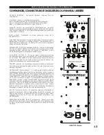
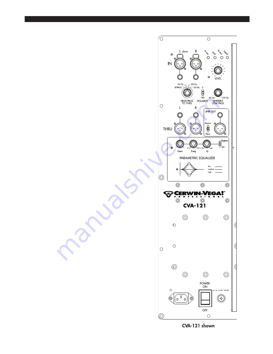
INDICATORS: illumination of LED indicates status of amplifier.
Power = electric current is live and present in the system
Limit
= the system is being driven to its maximum capacity (clipping)
Protect = the built-in amplifier has shut down to protect itself
Signal = a line-level signal is present in the system
IN L & R inputs: electronically balanced XLR and 1/4” phone
connectors accept input signal from line-level sources. IN L & R also
routes to THRU L & R outputs.
LEVEL: controls the master volume at the pre-amp stage.
HIGH PASS FILTER: when sending a full range signal through the
subwoofer to top cabinet, the HPF blocks LF signals below
indicated frequencies from reaching the top cabinet.
VARIABLE LOW PASS FILTER: when sending a full range signal to
the subwoofer, the variable LPF blocks HF signals above indicated
frequencies from reaching the subwoofer.
THRU L & R outputs: provide a loop-thru of the signals coming in
on the L and R inputs. The High Pass filter is active on these
outputs. These outputs and the High Pass filter are always active
regardless of whether the unit is in master or slave mode. Typically
these outputs are used for top cabinets.
POLARITY SWITCH: changes the polarity of the subwoofer, also
referred to as the “phase.” Listen and adjust for maximum bass.
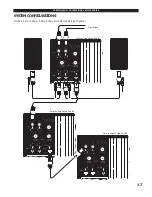
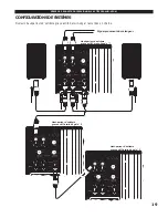
MASTER/SLAVE: This mode is used to provide the ability to adjust
multiple sub units from the master sub. When switched to MASTER,
all sub controls are functional and both L and R inputs are opera-
tional. The LINK OUT connector sums the input signals from both
L and R inputs and is used to send a signal to a sub in SLAVE mode.
When set to SLAVE mode, only the L input connector is active and
the LEVEL, POLARITY, and LOW PASS FILTER are inactive.
To
attach more subs, set them to SLAVE mode, use the LINK OUT of
the previous sub, and send this signal to the L IN on the SLAVE.
LINK OUT: Used to send a signal to a sub set to SLAVE mode.
When the sub is set to SLAVE mode, the LINK OUT provides a
summed signal of the L and R inputs. (See MASTER/SLAVE for
more information.)
PARAMETRIC EQUALIZER (CVA-121 only): one band full
parametric equalizer with adjustment of the Gain, Frequency, and
Q. The higher the setting, the narrower the frequency range
becomes that is being affected.
POWER SWITCH: turns the AC power of the unit on and off.
AC INPUT: input for attachment of the IEC power cord.
CERWIN-VEGA! PROFESSIONAL ACTIVE SERIES
11


