chapter 5000
page 53
1,2 - 2,0 t A.C.
SERVICE MANUAL
Electric
036-0410-07
CODE ALARM
DESCRIPTION
14
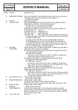
THERMIC SENS KO The values indicated by the temperature sensor of the inverter are always
checked and if they are out of range this warning appears.
- Replace the logic unit.
15
SAFETY
Replace the logic unit.
16
CAN BUS KO
Comunication failure between the logic units: traction (Master & Slave),
lifting, Mhyrio and all the cards. The alarm appears if:
- CAN H and / or CAN L signals deconnected
- there is no comunication from one logic unit.
If the problem starts from one card the system recognizes in which one:
CAN BUS KO 0A : I/O card
CAN BUS KO 05 : Lifting logic unit
CAN BUS KO 04 : Slave logic unit
CAN BUS KO
: Master logic unit (no suffix after the alarm message)
- Before replacing any logic unit it is suggested a preliminary check of the
CAN BUS connections.
Using the console, through connection numbersand selecting the
TESTER function, try to carry out a link with all the junction knots
toward the different logic units. Verify the links by, at least, one of the
signals from the field, i.e. microswitches, potentiometers. Where you
don’t reach the link, there is a line interruption.
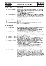
17
WAITING
Time lag fault on the CAN BUS comunication. The Master logic unit detects
FOR NODE
wich logic unit has generated the problem
#4 The Master logic unit receives the informations caming from the Slave
logic unitwith a time lag fault.
The fault can be caused by
- interference on the can bus. Check the CAN-BUS comunication.
- broken logic. Replace the traction logic unit.
#5 The Master logic unit receives the informations caming from the
Lifting logic unit with a time lag fault.
The fault can be caused by
- interference on the can bus. Check the CAN-BUS comunication.
- false contact. Check the connections of CAN H and CAN L wires.
- broken logic. Replace the lifting logic unit.
#9 The Master logic unit receives the informations caming from the
Mhyrio logic unit with a time lag fault.
The fault can be caused by
- interference on the CAN-BUS. Check the CAN-BUS comunication.
- false contact. Check the connections of CAN H and CAN L wires.
- broken logic. Replace the Mhyrio logic unit.
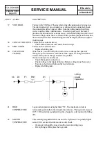
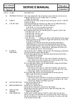
18
AUX OUTPUT KO
Failure on the contactor driver.
- Replace the traction unit.
19
DRIVER SHORTED
Failure on the contactor driver.
Check the main contactors coils and relevant wirings.
If the failure is not due to external causes, replace the traction logic unit.
20
CONTACTOR
Failure on the contactor driver.
DRIVER
- Replace the traction unit.
21
COIL SHORTED
Failure on the contactor driver. Check the main contactors coils and
relevant wirings. Control that there are no short-circuits in the wiring and
that the coil resistance value is correct. If the failure is not due to external
causes replace the logic unit.
Summary of Contents for BT BLITZ 312
Page 7: ...chapter A page 3 1 2 2 0 t A C SERVICE MANUAL Electric 036 0410 07 TECHNICAL DATA...
Page 8: ...chapter A page 4 1 2 2 0 t A C SERVICE MANUAL Electric 036 0410 07...
Page 9: ...chapter A page 5 1 2 2 0 t A C SERVICE MANUAL Electric 036 0410 07...
Page 11: ...chapter 0000 page 1 1 2 2 0 t A C SERVICE MANUAL Electric 036 0410 07 CHAPTER 0000 CHASSIS...
Page 175: ...chapter 5000 page 123 1 2 2 0 t A C SERVICE MANUAL Electric 036 0410 07 WIRING DIAGRAMS...
Page 176: ...chapter 5000 page 124 1 2 2 0 t A C SERVICE MANUAL Electric 036 0410 07...
Page 177: ...chapter 5000 page 125 1 2 2 0 t A C SERVICE MANUAL Electric 036 0410 07...
Page 178: ...chapter 5000 page 126 1 2 2 0 t A C SERVICE MANUAL Electric 036 0410 07...
Page 179: ...chapter 5000 page 127 1 2 2 0 t A C SERVICE MANUAL Electric 036 0410 07...
Page 180: ...chapter 5000 page 128 1 2 2 0 t A C SERVICE MANUAL Electric 036 0410 07...
Page 181: ...chapter 5000 page 129 1 2 2 0 t A C SERVICE MANUAL Electric 036 0410 07...
Page 182: ...chapter 5000 page 130 1 2 2 0 t A C SERVICE MANUAL Electric 036 0410 07...
Page 183: ...chapter 5000 page 131 1 2 2 0 t A C SERVICE MANUAL Electric 036 0410 07...
Page 184: ...chapter 5000 page 132 1 2 2 0 t A C SERVICE MANUAL Electric 036 0410 07...
Page 201: ...chapter 7000 page 1 1 2 2 0 t A C SERVICE MANUAL Electric 036 0410 07 CHAPTER 7000 MAST GROUP...
Page 217: ...chapter 8000 page 1 1 2 2 0 t A C SERVICE MANUAL Electric 036 0410 07 CHAPTER 8000 ATTACHEMENT...
Page 219: ...chapter 9000 page 1 1 2 2 0 t A C SERVICE MANUAL Electric 036 0410 07 CHAPTER 9000 OPTIONS...


