chapter 5000
page 74
1,2 - 2,0 t A.C.
SERVICE MANUAL
Electric
036-0410-07
MAIN MENU:
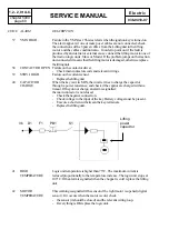
PARAMETER CHANGE (MASTER connection number 3)
MAIN MENU
PARAM. CHANGE
Press ENTER
Press ENTER
Select the program P on the dashboard before working with the main menu PARAMETER CHANGE.
Scroll the parameters using ROLL and save the new values pressing OUT and after ENTER
ACCELER/DELAY
determines the acceleration ramp.
RELEASE BRAKING
controls the deceleration ramp when the travel pedal is released.
INVERSION BRAKING
controls the deceleration ramp when the direction switch is inverted
during the travel.
PEDAL BRAKING
determines the deceleration ramp when the travel pedal is released and
thebrake pedal switch is closed.
SPEED LIMIT BRAKING
deceleration ramp when the pedal position is partly released, not
completely.
BRAKE CUTBACK
determines the deceleration ramp when the speed reduction input
becomes active and the motor slows down.
MAX SPEED FORWARD
determines the maximum speed in forward direction.
MAX SPEED BACKWARD
determines the maximum speed in backward direction.
CUTBACK SPEED 1
speed reduction when the cutback switch is active. Turtle function.
CUTBACK SPEED 2
speed reduction with brake pedal pressed.
CUTBACK SPEED 3
speed reduction enabled when the C10 signal is low.
CURVE CUT BACK
speed reduction in curve.
FREQUENCY CREEP
minimum speed when the forward or reverse switch is closed, but the
accelerator is slightly pressed.
MAXIMUM CURRENT
this changes the maximum current of the inverter.
ACC. SMOOTH
this delays the acceleration ramp from 0 hz to “stop smooth” value.
INV. SMOOTH
this delays the deceleration ramp of the inversion from “stop smooth”
value to 0 hz.
STOP SMOOTH
reference speed for the parameters ACC. SMOOTH and INV. SMOOTH
AUXILIARY TIME
time delay when an hydraulic steering function request is switched off.
DA2M2B C
CE 1.13
48V
280A
00000
Summary of Contents for BT BLITZ 312
Page 7: ...chapter A page 3 1 2 2 0 t A C SERVICE MANUAL Electric 036 0410 07 TECHNICAL DATA...
Page 8: ...chapter A page 4 1 2 2 0 t A C SERVICE MANUAL Electric 036 0410 07...
Page 9: ...chapter A page 5 1 2 2 0 t A C SERVICE MANUAL Electric 036 0410 07...
Page 11: ...chapter 0000 page 1 1 2 2 0 t A C SERVICE MANUAL Electric 036 0410 07 CHAPTER 0000 CHASSIS...
Page 175: ...chapter 5000 page 123 1 2 2 0 t A C SERVICE MANUAL Electric 036 0410 07 WIRING DIAGRAMS...
Page 176: ...chapter 5000 page 124 1 2 2 0 t A C SERVICE MANUAL Electric 036 0410 07...
Page 177: ...chapter 5000 page 125 1 2 2 0 t A C SERVICE MANUAL Electric 036 0410 07...
Page 178: ...chapter 5000 page 126 1 2 2 0 t A C SERVICE MANUAL Electric 036 0410 07...
Page 179: ...chapter 5000 page 127 1 2 2 0 t A C SERVICE MANUAL Electric 036 0410 07...
Page 180: ...chapter 5000 page 128 1 2 2 0 t A C SERVICE MANUAL Electric 036 0410 07...
Page 181: ...chapter 5000 page 129 1 2 2 0 t A C SERVICE MANUAL Electric 036 0410 07...
Page 182: ...chapter 5000 page 130 1 2 2 0 t A C SERVICE MANUAL Electric 036 0410 07...
Page 183: ...chapter 5000 page 131 1 2 2 0 t A C SERVICE MANUAL Electric 036 0410 07...
Page 184: ...chapter 5000 page 132 1 2 2 0 t A C SERVICE MANUAL Electric 036 0410 07...
Page 201: ...chapter 7000 page 1 1 2 2 0 t A C SERVICE MANUAL Electric 036 0410 07 CHAPTER 7000 MAST GROUP...
Page 217: ...chapter 8000 page 1 1 2 2 0 t A C SERVICE MANUAL Electric 036 0410 07 CHAPTER 8000 ATTACHEMENT...
Page 219: ...chapter 9000 page 1 1 2 2 0 t A C SERVICE MANUAL Electric 036 0410 07 CHAPTER 9000 OPTIONS...


