chapter 5000
page 26
1,2 - 2,0 t A.C.
SERVICE MANUAL
Electric
036-0410-07
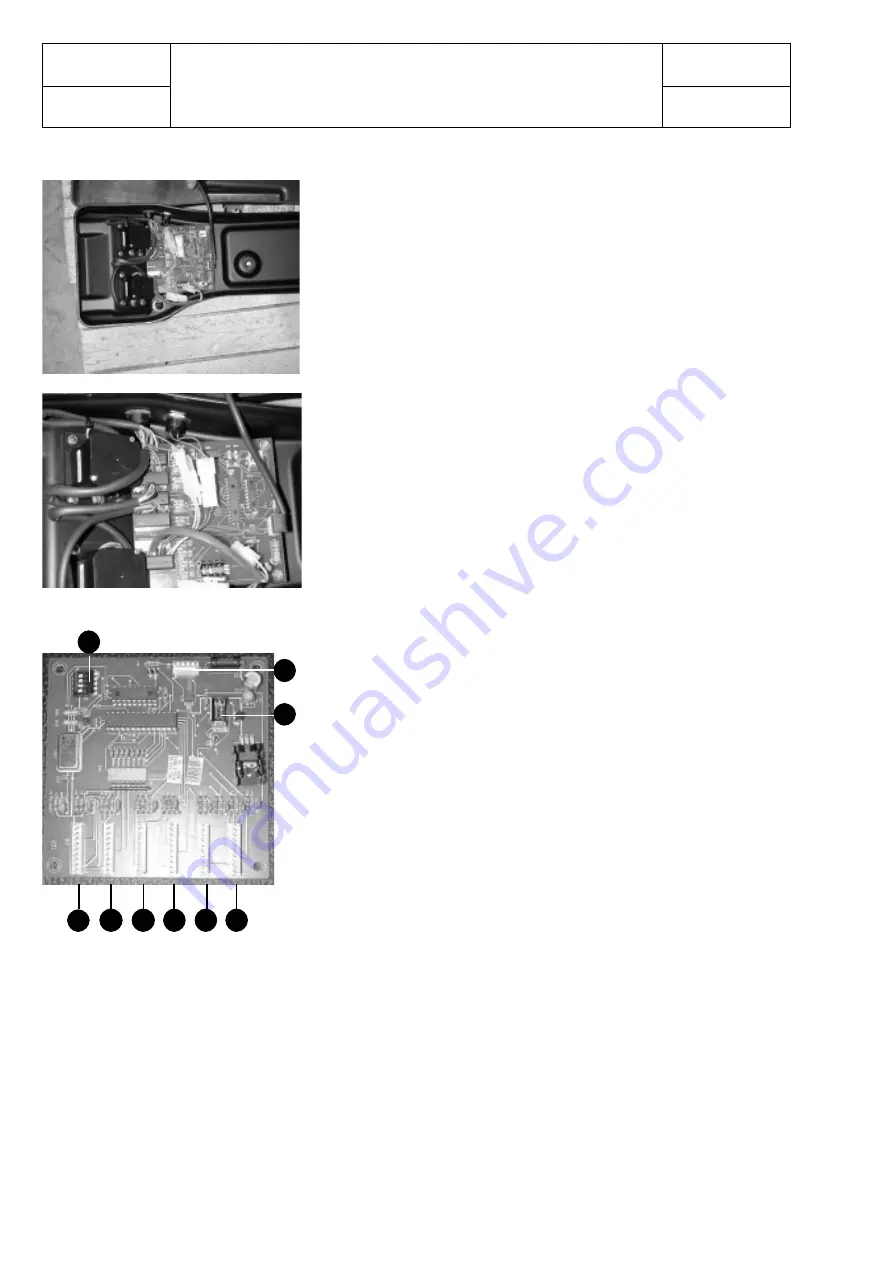
The arm card, located inside the seat arm is present in fingertips /
joysticks truck version. It is supplied by the dc / dc converter wi
t
h
24 V.
The fingertips /joysticks version requires also the use of an
additional logic unit (Mhyrio)
FUNCTIONS
It controls and converts from analogic to digital the fingertips /
joysticks potentiometers signals in order to drive, via Mhyrio, the
electric distibutor, equipped with solenoid valves.
It also controls the push buttons signals of the forward / backward
directions and of the horn.
CONNECTIONS
The card is connected by the cab-bus wiring to the light card
SETTINGS
In order to inform the card about the potentiometers type used, the
following setting is required:
JOYSTICKS
all the dip switches (layout, pos. 9) are
setted on OFF position.
FINGERTIPS
the dip switch n° 2 (layout, pos. 9) is setted
on ON position
(In case this is not enabled the logic unit
shows the alarm INCORRECT START)
The potentiometres replacement does not require any calibration
by the console
ARM CARD
LAY-OUT
1. Connector for the lifting potentiometer (finger/joystick)
2. Connector for the tilt potentiometer (finger/joystick)
3. Connector for the sideshift potentiometer (finger/joystick)
4. Connector for the 4th way potentiometer (finger/joystick)
5. Connector for the 5th way potentiometer (finger/joystick)
6. Connector for the auxiliary funtions: push buttons for the
horn and for the directions.
7. Connector for the CAN-BUS
8. Connector for the programming of the microchip.
9. Dip switches
see wiring diagram
1
2
5
4
3
6
7
8
9
Summary of Contents for BT BLITZ 312
Page 7: ...chapter A page 3 1 2 2 0 t A C SERVICE MANUAL Electric 036 0410 07 TECHNICAL DATA...
Page 8: ...chapter A page 4 1 2 2 0 t A C SERVICE MANUAL Electric 036 0410 07...
Page 9: ...chapter A page 5 1 2 2 0 t A C SERVICE MANUAL Electric 036 0410 07...
Page 11: ...chapter 0000 page 1 1 2 2 0 t A C SERVICE MANUAL Electric 036 0410 07 CHAPTER 0000 CHASSIS...
Page 175: ...chapter 5000 page 123 1 2 2 0 t A C SERVICE MANUAL Electric 036 0410 07 WIRING DIAGRAMS...
Page 176: ...chapter 5000 page 124 1 2 2 0 t A C SERVICE MANUAL Electric 036 0410 07...
Page 177: ...chapter 5000 page 125 1 2 2 0 t A C SERVICE MANUAL Electric 036 0410 07...
Page 178: ...chapter 5000 page 126 1 2 2 0 t A C SERVICE MANUAL Electric 036 0410 07...
Page 179: ...chapter 5000 page 127 1 2 2 0 t A C SERVICE MANUAL Electric 036 0410 07...
Page 180: ...chapter 5000 page 128 1 2 2 0 t A C SERVICE MANUAL Electric 036 0410 07...
Page 181: ...chapter 5000 page 129 1 2 2 0 t A C SERVICE MANUAL Electric 036 0410 07...
Page 182: ...chapter 5000 page 130 1 2 2 0 t A C SERVICE MANUAL Electric 036 0410 07...
Page 183: ...chapter 5000 page 131 1 2 2 0 t A C SERVICE MANUAL Electric 036 0410 07...
Page 184: ...chapter 5000 page 132 1 2 2 0 t A C SERVICE MANUAL Electric 036 0410 07...
Page 201: ...chapter 7000 page 1 1 2 2 0 t A C SERVICE MANUAL Electric 036 0410 07 CHAPTER 7000 MAST GROUP...
Page 217: ...chapter 8000 page 1 1 2 2 0 t A C SERVICE MANUAL Electric 036 0410 07 CHAPTER 8000 ATTACHEMENT...
Page 219: ...chapter 9000 page 1 1 2 2 0 t A C SERVICE MANUAL Electric 036 0410 07 CHAPTER 9000 OPTIONS...


