background image

ReCon T Energy Logger
User manual

LED indicators

Some instruments do not include LCD to display measurements and information, so LEDs´ behavior 

is modified from firmware version V2.60 on to provide the user with more information on the instrument´s 
status.

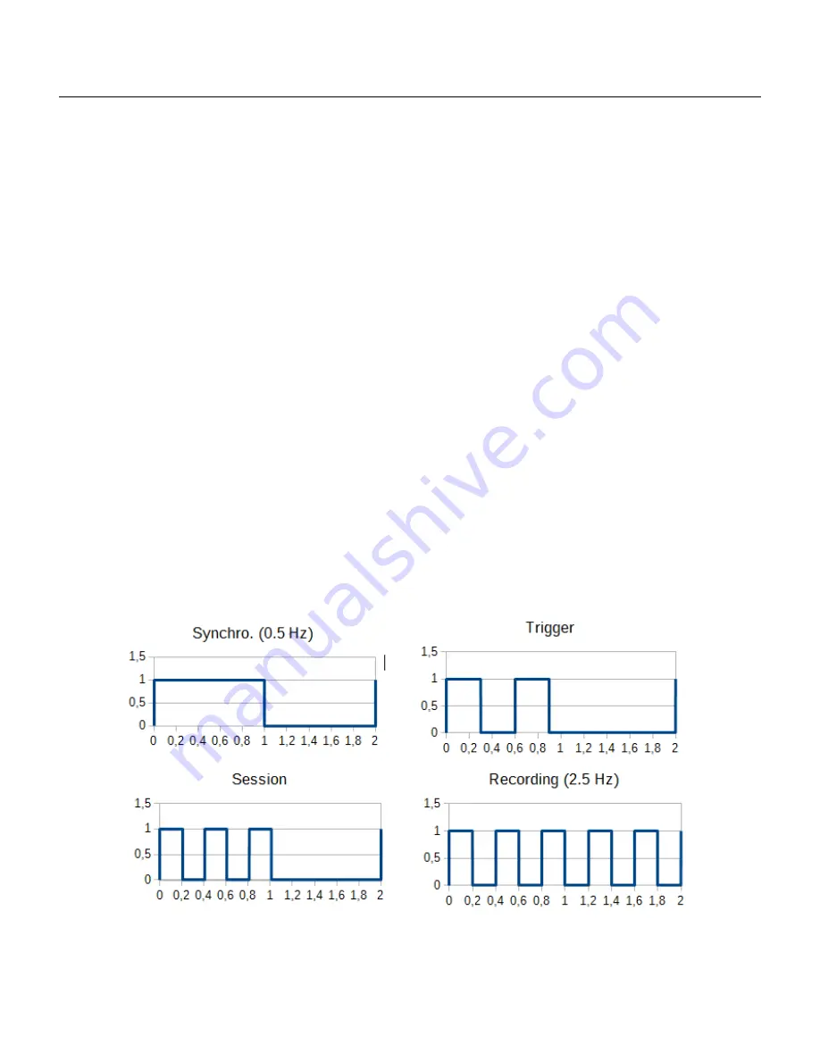
There are basically 4 blinking modes that reflect measurement and recording status, plus 2 different 

colors for providing further information. If memory is full, red LED will be active blinking (or steady when 
measurement is stopped). Otherwise, green LED will be blinking and red LED will be off (unless there´s a 
serious hardware malfunction and red LED is permanently on):

Waiting for time synchronizing: as said before, measurements must be synchronized with multiples 
of Recording interval. Once recording is allowed to start (through any method of those explained 
before), there is a certain time interval when the instrument is waiting to align measurements with 
specified recording interval. Then, blinking of LED (green or red if memory is full) shows 0.5 Hz.

Waiting for trigger to occur: LED (green or red if memory is full) blinks twice in one second and 
then it is off for another second.

Waiting for programmed session to start: LED (green or red if memory is full) blinks three times in 
one second and then it is off for another second.

Recording: once recording has been started by any method (continuous, triggered, time programmed)
and synchronizing period has elapsed, LED (green or red if memory is full) blinks at 2.5 Hz.

19/39

Figure 14: Led blinking code

Summary of Contents for ReCon T

Page 1: ...ReCon T Energy Logger User manual...

Page 2: ...e and TCP IP connection 23 MODBUS in ReCon T 24 Available real time measurements via MODBUS 24 ReCon T built in web server 26 Bluetooth configuration and use 27 Windows XP 27 Windows 7 31 Windows 10 3...

Page 3: ...30 Figure 32 Windows XP End of Wizard outgoing port highlighted 30 Figure 33 Windows XP ReCon T connection ready 30 Figure 34 Bluetooh connection in MEDCALScope 31 Figure 35 Windows XP Make Bluetooth...

Page 4: ...ReCon T Energy Logger User manual Figure 57 Toshiba end of wizard 38 Figure 58 Toshiba list of devices 39 Figure 59 Toshiba authentication dialog 39 4 39...

Page 5: ...web server documentation CABL 1 6 07 02 2013 Added information on measurement methods RACB 1 7 30 10 2015 Bluetooth information added MJCG 1 8 05 03 2020 Complete revision of the document Added new f...

Page 6: ...d boots helmet and any other required individual protection equipment 6 Do not operate the ReCon T Energy Logger in explosive hazardous areas 7 Use only insulated current probe s test leads and adapte...

Page 7: ...rs have a marked arrow to indicate the positive sense of current The most common situation you will use the instrument for is analyzing the energy consumption of an installation Connect the flexible c...

Page 8: ...ly disconnect the instrument in order to finish the recording session Connecting the ReCon T Energy Logger To install the ReCon T Energy Logger follow these steps 1 Place the ReCon T Energy Logger at...

Page 9: ...the ReCon T and downloading the recorded information are done via the MEDCALScope PC application Simply click on the Set up button The set up screen is divided in 7 different areas 9 39 Figure 1 Tool...

Page 10: ...e used to access ReCon T Either CESINEL protocol if you intend to download data via TCP IP using MEDCALScope or ModBus TCP if the instrument is integrated in a larger automation network that requires...

Page 11: ...a wide selection of choices between 115 V and 480 V 3 Measuring in High Voltage HV sometimes the load to be analyzed is fed directly from high voltage larger than 1 kV It is possible to measure in th...

Page 12: ...second option enables S measurement from Vrms and Irms and Q calculation from measured P and S Q is non active power then 7 Next panel is only present when instrument runs a firmware equal to or high...

Page 13: ...and time as PC synchronizes the ReCon T internal clock with the PC s clock 4 Reset energy counter clears the internal energy registers of the ReCon T These registers are not cleared when memory is era...

Page 14: ...sensors or even an absence of current sensors from firmware V2 61 on voltage only recording session is possible so there is no need to attach current sensors what makes transportation and installatio...

Page 15: ...er clicks Apply and start recording and stops recording when Erase recorded data is clicked The instrument measures and records data even during downloading of data setting up of the instrument unless...

Page 16: ...date and time is reached If memory is setup as linear memory the programmed session could end before stop date and time If circular memory is selected programmed session will end at the specified dat...

Page 17: ...rted The available trigger variables are the three measured voltages and currents Once the trigger is fired the recording lasts until memory is full if linear memory is selected or user stops it via M...

Page 18: ...Figure 10 Connection for 3 Phase Wye Star topology 2 3 Delta triangle topology Figure 11 Connection for 3 Phase Delta Triangle topology 3 1 Phase with Neutral topology Figure 12 Connection for single...

Page 19: ...zing as said before measurements must be synchronized with multiples of Recording interval Once recording is allowed to start through any method of those explained before there is a certain time inter...

Page 20: ...local IP address of the unit is enough to access the data Medcal S cop e software provides an Instrument Name IP Address table which will be stored in memory and therefore available every time Medcal...

Page 21: ...er s configuration utility if the router is DHCP configured or must be provided by the ISP internet server provider from whom you rent your internet connection if a static IP address is rented Routers...

Page 22: ...e software With the configuration of the previous figures and supposing that our router s public IP address is 80 10 3 247 14 we could access data via MedcalScope Modbus software or web browser from a...

Page 23: ...Then when download or setup actions are triggered through menu items or toolbar buttons a TCP IP selector dialog appears see Figure 12 so that the user can choose an existing item or add a new one to...

Page 24: ...t signed8 decimal W9 1 L2 Mean Active power of 1 second reading 16 bit signed decimal W 2 L3 Mean Active power of 1 second reading 16 bit signed decimal W 3 Total Mean Active power of 1 second reading...

Page 25: ...Energy 16 bit 24 L2 Mid Low word of Accumulated Active Energy 16 bit 25 L2 Lowest word of Accumulated Active Energy 16 bit Wh 26 L3 Highest word of Accumulated Active Energy 16 bit 27 L3 Mid High word...

Page 26: ...ReCon T Energy Logger User manual 26 39...

Page 27: ...vious sections on how to access a ReCon T from outside inside its LAN The web page has an auto refresh interval of 5 seconds although the user may always refresh the web page via web browser commands...

Page 28: ...PC s operating system Windows XP 1 Start Control panel or double click Bluetooth icon Bluetooth devices Add a new Bluetooth device 2 Make sure that you check the My device is configured and ready to b...

Page 29: ...and then type that key in the associated field13 6 The PC will connect to the ReCon T instrument exchange access keys and install virtual serial ports 13 The key is by default equal to the 4 last digi...

Page 30: ...serial ports created Since the ReCon T instrument will never start the communication and will always be treated as slave during the process we must pay attention to the Output serial port 9 The ReCon...

Page 31: ...n in the notification area option 12 If you are not going to work with the Bluetooth ReCon T device for a long time it is recommend ed to remove the instrument from the Bluetooth devices list since th...

Page 32: ...ReCon T Energy Logger User manual Windows 7 1 Start Control panel or double click Bluetooth icon Add new device 32 39 Figure 37 Windows 7 Control Panel Figure 38 Windows 7 Add new device...

Page 33: ...ded key and click Next The PC will connect with the ReCon T instrument and will install the device controller software A pop up message will appear when the process is finished and the device will be...

Page 34: ...n T icon and select Properties Go to Services tab and the virtual serial port identifier will be displayed there 34 39 Figure 42 Windows 7 End of installation of device Figure 43 Windows 7 Device prop...

Page 35: ...Con T device for a long time it is recommended to remove the instrument from the Bluetooth devices list since the virtual serial ports are not automatically removed and new ones are created for every...

Page 36: ...new device 2 Click on the ReCon T instrument and wait for Windows to ask for PIN Enter PIN code and click Connect 36 39 Figure 45 Windows 10 Bluetooth and devices Figure 46 Windows 10 add Bluetooth d...

Page 37: ...s and printers right click on ReCon T and click Properties to guess COM port under Services tab 37 39 Figure 50 Windows 10 devices and printers in setup Figure 52 Windows 10 properties of paired ReCon...

Page 38: ...th stack different than the one provided by Windows Toshiba for instance you must use the tools provided by the manufacturer 1 Create a new connection 38 39 Figure 53 Bluetooh icon Figure 55 Toshiba B...

Page 39: ...rgy Logger User manual 2 An access key will be required the first time that you try to connect with the ReCon T instrument either using MEDCALScope or the assistant 39 39 Figure 59 Toshiba authenticat...

Reviews: